


13- 11- 603
Page 9
SECTION 2
INSTALLATION, COOLERS AND WATER SYSTEMS
GENERAL
-- On receipt of the unit, check for any dam-
age that may have occurred during transit or handling.
Report any damage or missing parts as soon as pos-
sible.
Do not electric weld on the compres-
sor or base; bearings can be damaged
by passage of current.
LIFTING UNIT
-- Proper lifting and/or transporting
methods must be used to prevent damage. Towmotor
fork clearance is provided by the equipment isolators
bolted to the base of the unit. The unit may also be
moved into location by rolling on bars.
Lift compressor unit by base only. Do
not use other places such as motor,
compressor or discharge manifold
piping as lifting points.
The eyebolts or lugs provided on the
motor are for lifting the motor only
and should not be used to lift any
additional weight. All eyebolts must
be securely tightened. When lifting
the motor the lifting angle must not
exceed 15 degrees. Failure to observe
this warning may result in damage to
equipment or personal injury.
LOCATION
-- The compressor should be installed in a
clean, well-- lighted, and ventilated area with ample
space all around the unit for maintenance. Select a
location that provides a cool, clean, and dry source of
air. In some cases it may be necessary to install the air
filter at some distance from the compressor to obtain
proper air supply.
Do not install this compressor in a
location that may be subject to tem-
peratures below 32
_
F. (0
_
C.).
Below freezing temperatures will
cause damage to the compressor.
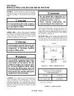
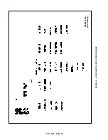
The air-- cooled unit requires cooling air as well as air to
the compressor inlet. Proper ventilation MUST be pro-
vided; hot air must be exhausted from the compressor
operating area. A typical inlet-- outlet air flow arrange-
ment is shown in FIGURE 2-- 1.
Air- Cooled Units
-- An air cooled heat exchanger and
aftercooler is supplied as standard equipment on all
air-- cooled units. The air cooled motors and fans are
mounted within the cooling module; air is drawn into the
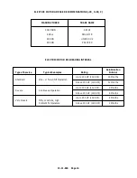
FIGURE 2--1 -- TYPICAL COMPRESSOR ROOM
* 80
_
F (27
_
C) Inlet Air
Minimum Air Flow* For Compression
And Cooling -- Cubic Feet/Minute
(Cubic Meters/Minute)
HP (KW)
Air Cooled
20 -- 30 (15 -- 22)
5,200 (147)
FIGURE 2--2 -- AIR FLOW CHART
Summary of Contents for ROTORCHAMP RCOF20
Page 13: ...13 11 605 Page 4 FIGURE 1 6 AIR WATER SCHEMATIC 300EWC797 B Ref Drawing ...
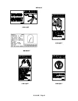
Page 16: ...13 11 605 Page 7 DECALS 206EAQ077 300EWC077 301EWC077 211EAQ077 207EAQ077 ...
Page 17: ...13 11 605 Page 8 DECALS 216EAQ077 206EWD077 222EAQ077 221EAQ077 208EAQ077 ...
Page 31: ...13 11 605 Page 22 FIGURE 4 2 FLOW CHART FOR SET UP PROGRAMMING 300EWC1255 Ref Drawing ...
Page 41: ...13 11 605 Page 32 FIGURE 4 6 CONTROL TUBING SCHEMATIC 300EWC797 B Ref Drawing ...
Page 45: ...13 11 605 Page 36 FIGURE 4 10 WIRING DIAGRAM FULL VOLTAGE 301EWC546 A Ref Drawing ...
Page 46: ...13 11 605 Page 37 FIGURE 4 11 WIRING DIAGRAM WYE DELTA 302EWC546 A Ref Drawing ...
Page 47: ...13 11 605 Page 38 FIGURE 4 12 AUTO SENTRY W CONTROLLER DISPLAY ...
Page 49: ...13 11 605 Page 40 FIGURE 5 1 OIL LEVEL SIGHT GLASS 306EWC797 A Ref Drawing ...
Page 50: ...13 11 605 Page 41 FIGURE 5 2 FLOW DIAGRAM AIR COOLED 300EWC797 A Ref Drawing ...


