


13- 11- 603
Page 13
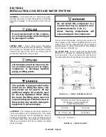
COMPRESSOR
INJECTION
WATER
SYSTEM
CHECK
-- The following readings are based on an am-
bient temperature of 80
_
F. inlet cooling air on air--
cooled units with the cooling system in good, clean
condition. The compressor should be at operating tem-
perature at the time of the checks. One-- half hour of
loaded operation is usually sufficient to reach level-- out
operating temperatures.
Air and Water Discharge Temperature
-- 105
_
to
125
_
F. -- Read on the “AUTO SENTRY
R
-- W” control
panel.
Compressor Injection Water Inlet Temperature
--
90
_
to 110
_
F. -- Check anywhere on the line from the
heat exchanger to the compressor inlet.
Water Injection Cooler Temperature Differential
(Air Cooled Heat Exchanger)
-- The water tempera-
ture differential depends on the temperature of the air
at the water injection cooler fan and the cleanliness of
the core faces. As ambient temperatures and core re-
strictions increase, the injection water outlet tempera-
ture will increase. The injection water outlet tempera-
ture is approximately the same as the package exhaust
air temperature.
The outlet temperature may be
checked by installing a tee in the water line between the
separator/reservoir and the cooler.
Water Injection Cooler Pressure Differential (Air
Cooled Heat Exchanger)
-- 5 to 7 psid -- Check injec-
tion water pressure differential in the same place as
temperature. (See above.)
ELECTRICAL WIRING
-- Standard Units -- The
RotorChamp
R
compressor is factory wired for all start-
er to motor and control connections for the voltage spe-
cified on the order. It is necessary only to connect the
unit starter to the correct power supply. The standard
unit is supplied with an open drip-- proof motor, a NEMA
12 starter and control enclosure. See “Location” para-
graph for distance to nearest obstruction on starter and
control box sides of the unit.
Electrical shock can cause injury or
death. Open main disconnect switch,
tag and lockout before working on
starter/control box.
GROUNDING
-- Equipment must be grounded in ac-
cordance with Section 250 of the National Electrical
Code.
Failure to properly ground the com-
pressor package could result in con-
troller malfunction.
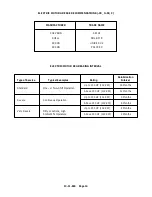
MOTOR LUBRICATION
-- Long time satisfactory op-
eration of an electric motor depends in large measure
on proper lubrication of the bearings. The charts on the
next page show recommended grease qualities and re-
greasing intervals for ball bearing motors. For addition-
al information, refer to the motor manufacturer’s
instructions.
The following procedure should be used in regreasing:
1.
Stop the unit.
2.
Disconnect, tag and lockout the unit from the pow-
er supply.
3.
Remove the relief plug and free hole of hardened
grease.
4.
Wipe lubrication fitting clean and add grease with
a hand-- operated grease gun.
5.
Leave the relief plug temporarily off. Reconnect
the unit and run for about 20 minutes to expell the
excess grease.
6.
Stop the unit. Replace the relief plug.
7.
Restart the unit.
Rotating machinery can cause injury
or death. Open main disconnect, tag
and lockout power supply to the start-
er before working on the electric mo-
tor.
Summary of Contents for ROTORCHAMP RCOF20
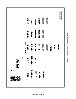
Page 13: ...13 11 605 Page 4 FIGURE 1 6 AIR WATER SCHEMATIC 300EWC797 B Ref Drawing ...
Page 16: ...13 11 605 Page 7 DECALS 206EAQ077 300EWC077 301EWC077 211EAQ077 207EAQ077 ...
Page 17: ...13 11 605 Page 8 DECALS 216EAQ077 206EWD077 222EAQ077 221EAQ077 208EAQ077 ...
Page 31: ...13 11 605 Page 22 FIGURE 4 2 FLOW CHART FOR SET UP PROGRAMMING 300EWC1255 Ref Drawing ...
Page 41: ...13 11 605 Page 32 FIGURE 4 6 CONTROL TUBING SCHEMATIC 300EWC797 B Ref Drawing ...
Page 45: ...13 11 605 Page 36 FIGURE 4 10 WIRING DIAGRAM FULL VOLTAGE 301EWC546 A Ref Drawing ...
Page 46: ...13 11 605 Page 37 FIGURE 4 11 WIRING DIAGRAM WYE DELTA 302EWC546 A Ref Drawing ...
Page 47: ...13 11 605 Page 38 FIGURE 4 12 AUTO SENTRY W CONTROLLER DISPLAY ...
Page 49: ...13 11 605 Page 40 FIGURE 5 1 OIL LEVEL SIGHT GLASS 306EWC797 A Ref Drawing ...
Page 50: ...13 11 605 Page 41 FIGURE 5 2 FLOW DIAGRAM AIR COOLED 300EWC797 A Ref Drawing ...


