6.0 Operation
23
6.9.11 Contrast Control (Serial Numbers 080075 and Above)
The contrast of the display can be adjusted by first pushing the hidden button on the front of the
control panel and using the left or right arrow keys to fine tune the contrast.
6.10 Manual Backgauge Control
6.10.1 Backgauge Glide Control
The backgauge can be moved manually by use of the backgauge glide control. Press towards the
operator for forward travel and away from the operator for reverse travel. The further away from
center that the actuator is pushed, the faster the backgauge will travel.
6.10.2 Backlash Indicator
To insure accurate cuts, the backgauge must be brought to the cut position from the rear of the table.
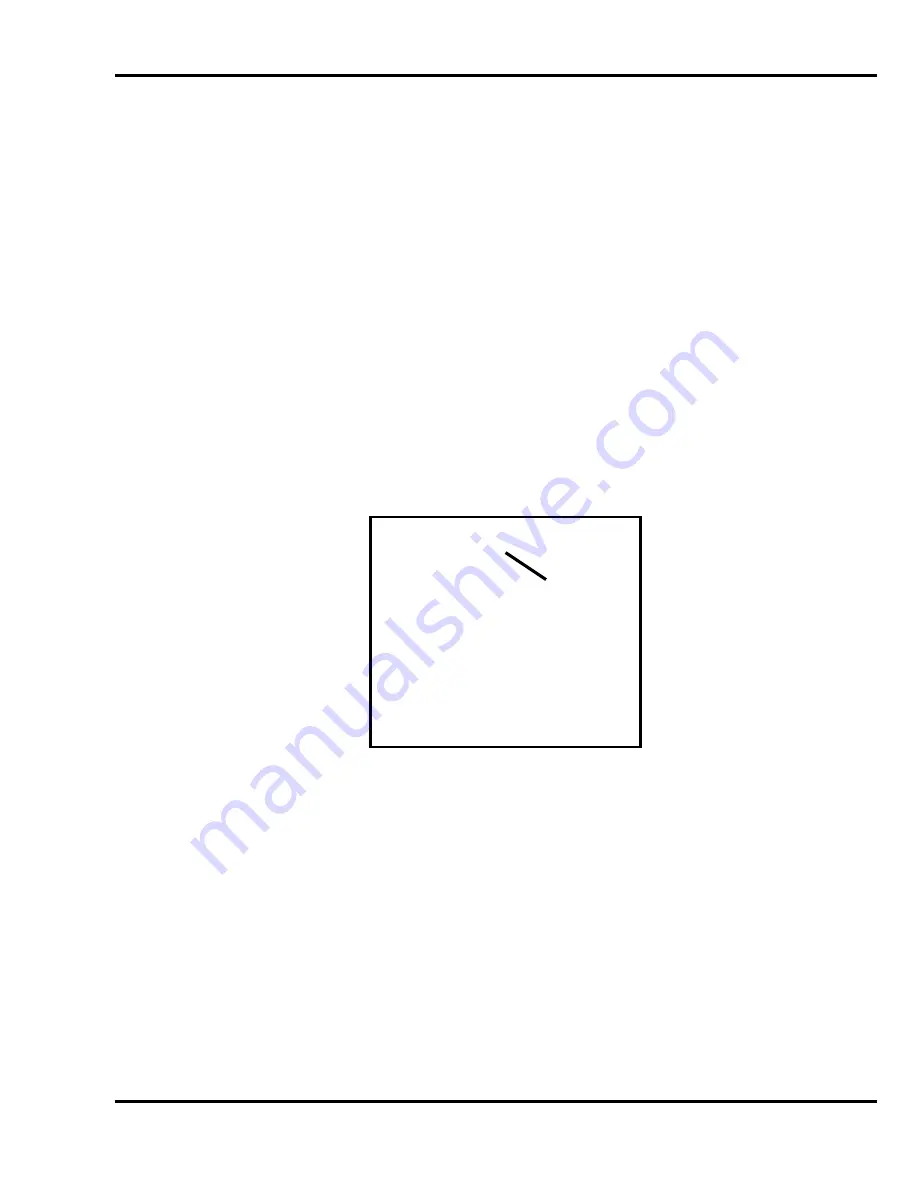
In the display, to the right of the backgauge position, there is a small arrow to indicate reverse travel
(Figure 20). This arrow should be off when making a cut. Moving back past your cut position, then
forward to it, compensates for any play in the backgauge nut and leadscrew.
6.11 Send Mode
Figure 20
The send mode is the first screen displayed after the backgauge is preset. From this screen the
backgauge can be positioned with the backgauge pinpoint control or by entering a value and pressing
the SEND key. When
the send value is less than approximately 4” and the electric eyes are
obstructed, the push out button must be held in for the backgauge to continue moving to the send
position. A mathematical expression can also be entered as a send value. Simply type the
expression and press SEND. You can also enter an equation, which begins with the current
backgauge position. For example, if you want to send the backgauge 2” forward from its current
position, just press [-] [2] and SEND.
The send mode screen can also be used for doing math calculations that are larger than the
backgauge’s reverse limit. In this case, you must press ENTER to have the result displayed on the
screen.
5.000
in /\
>_
A) Maint
B) Job
Reverse
Indicator
Arrow


