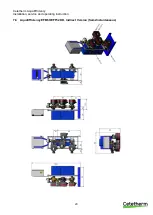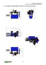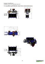
Cetetherm AquaEfficiency
Installation, service and operating instruction
14
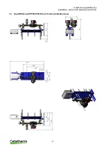
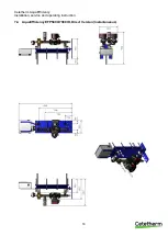
Installation of a Solarflow unit
6.1
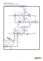
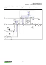
Operating principle Solarflow
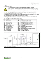
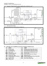
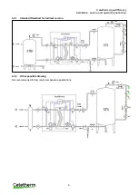
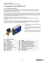
In the flowchart RS means a renewable source, eg solar, heat pump, condensate or else recover unit.
The 3-port mixing valve is activated only if temperature in STP or RS is hot enough, to limit DHW over heating
on S1.
Temperature on Pt1 is compared with S2 and allows or not, the primary pump, of the AquaEfficiency, to be
started.
If Pt1< S2+
ΔT then the primary pump is stopped. ΔT (
DT Recov_Min
) by default 5° is set in
Thanks to the AquaEfficiency control, the temperature at S3 is compared with the temperature at S2 to adjust
the primary flow rate and obtain low temperature returns on primary side.
The “leaking flow” on secondary side, coming from the recycling loop, allows S2 sensor to be irrigated and to
keep SolarF
low “awaken” without the need of any flow switch.
If a flow switch must be used because of leaking flow could not be installed, connect it on Remote control
contact terminal or on pump´s start/stop contact.
6.2
Flowchart Solarflow
ID.
NAME
ID.
NAME
CW
Cold Water inlet
Pt1
Primary vessel temperature sensor
DC
Drain valve
S1
DHW temperature sensor (master)
DHW
Domestic Hot water
S2
Secondary inlet temperature sensor
HE
Heat Exchanger
S3
Primary return temperature sensor
NR
Non Return Valve
V
Shut-off valve
PP
Primary pump
V3V
3-port control valve with actuator
PR
DHWC pump
VR
Balancing valve
PRV
Safety valve
STP
Primary storage tank
RS
Renewable source
STS
Secondary storage tank


