11
11
Cable
entry
area
Skid
plate
Access
door
~
1
6
4
200
230
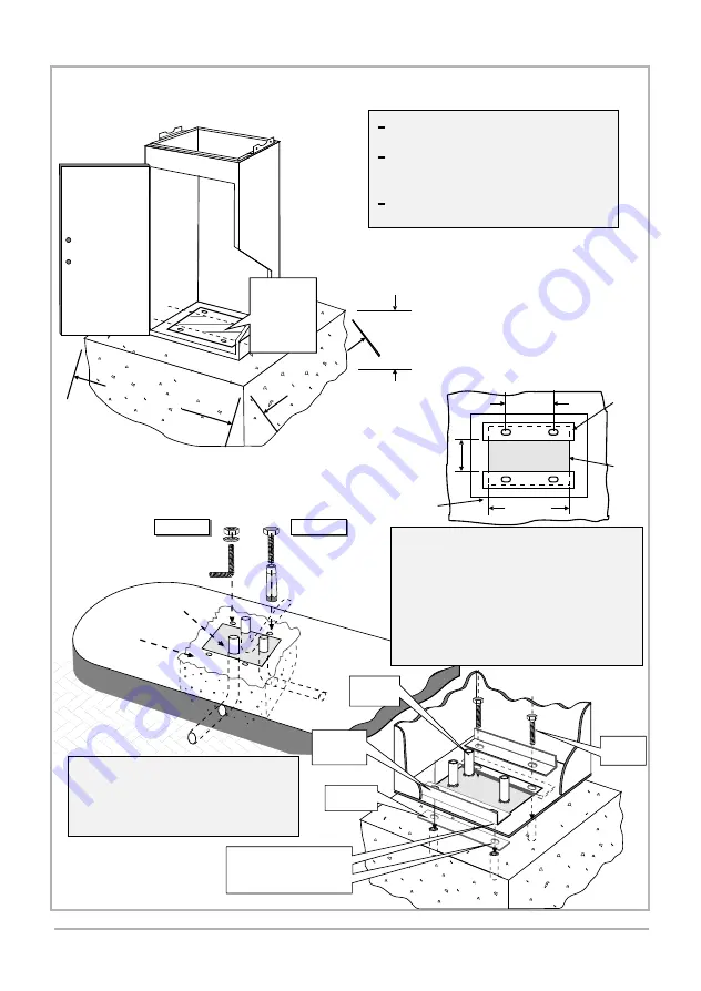
7.1 POSITIONING
7.0 INSTALLATION
Determine correct position for barrier .
Check orientation of door - see Section
5.0
Prepare hole for concrete foundation
500 x 500 x 300mm.
3
0
0
m
m
CABLE
ENTRY
AREA
(See section
7.2)
500mm
50
0m
m
7.2 BOLTING DOWN ARRANGEMENT
7.2.1 Alternative 1
EITHER
OR
ANCHOR
BOLTS
M16
CABLE
ENTRY
AREA
CONCRETE
SLAB
M16 x 150
RAWL BOLTS
- Throw concrete slab approximately
500 x 500 x 300 mm deep;
- Install cable conduits, make sure
conduits exit in cable entry area.
- Leave approximately 50 mm of conduit
protruding above concrete base;
- Concrete in anchor bolts or fit rawl
bolts later. Use skid plates as templates for
anchor / rawl bolt positioning, if required.
SKID PLATE
HOLDING
DOWN
ANGLE
CABLE
CONDUIT
M16X150
RAWL
BOLTS
NOTE: Enclosure base is clamped
between skid plates and
holding down angles.
APPLY GREASE TO CONTACT
AREA OF TOP OF SKID PLATE
AND BOTTOM OF HOLDING
DOWN ANGLE
Summary of Contents for CP71
Page 2: ...2 2...
Page 4: ...4 4...
Page 7: ...7 7 4 2 DETERMINATION OF OPERATIONAL MODE...
Page 16: ...16 16...
Page 21: ...21 21...
Page 28: ...28 28...
Page 38: ...34 34 38 38...
Page 39: ...39 39...


