background image

Page 2

For technical questions, please call 1-888-866-5797.

Item 33497 


SA

FETY

OPERA

TI

O

N

MAINTENANCE

SETUP

Table of Contents

Safety ........................................................................2
Specifications ............................................................4
Setup .........................................................................4
Operation ...................................................................8

Maintenance ..............................................................9
Parts List and Diagram .............................................10
Warranty ...................................................................12

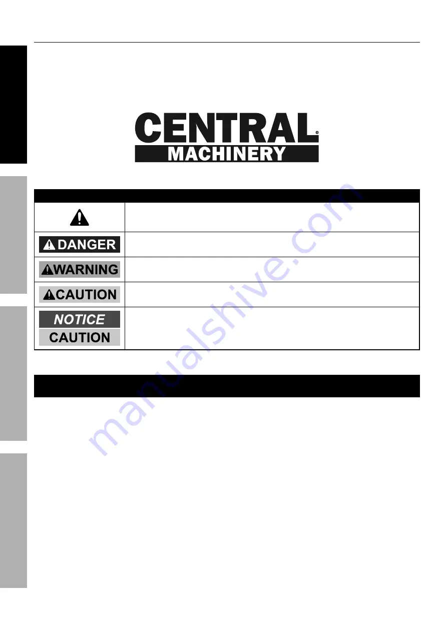
WARNING SYMBOLS AND DEFINITIONS

This is the safety alert symbol.  It is used to alert you to potential 

personal injury hazards.  Obey all safety messages that 

follow this symbol to avoid possible injury or death.

Indicates a hazardous situation which, if not avoided,  

will result in death or serious injury.

Indicates a hazardous situation which, if not avoided,  

could result in death or serious injury.

Indicates a hazardous situation which, if not avoided,  

could result in minor or moderate injury.

Addresses practices not related to personal injury.

IMPORTANT SAFETY INFORMATION

WARNING Read all safety warnings and instructions. 

Failure to heed these markings may result in 

personal injury and/or property damage.  

Save all warnings and instructions for future reference.

The warnings, precautions, and instructions discussed in this manual cannot cover all possible 

conditions and situations that may occur.  The operator must understand that common sense and 

caution are factors, which cannot be built into this product, but must be supplied by the operator.

1.  Keep hands away from arbor plates 

and press pin during use.

2.  Do not move workpiece while compressed.

3.  Release load before service or maintenance.

4.  Bolt to floor before use.

5.  Keep area under arbor plates clear.  If arbor 

plates rest on obstruction (i.e. bolt, debris, 

etc.), it creates an uneven press, causing 

excess stress and possible breakage.

6.  Avoid off-center loads.  Do not operate if 

workpiece tilts or binds during compression.

7.  STOP and release compression if you suspect 

imminent structural failure.  If safe, inspect 

thoroughly and reposition before proceeding.

8.  Do not compress springs or other elastic 

objects.  They could disengage hazardously.

9.  Wear ANSI-approved safety goggles, 

heavy-duty work gloves, and steel-toe 

work boots during set up and/or use.

10. Keep bystanders out of work area.

Summary of Contents for 33497

Page 1: ...n unpacking make sure that the product is intact and undamaged If any parts are missing or broken please call 1 888 866 5797 as soon as possible Copyright 2022 by Harbor Freight Tools All rights reserved No portion of this manual or any artwork contained herein may be reproduced in any shape or form without the express written consent of Harbor Freight Tools Diagrams within this manual may not be ...

Page 2: ...ave all warnings and instructions for future reference The warnings precautions and instructions discussed in this manual cannot cover all possible conditions and situations that may occur The operator must understand that common sense and caution are factors which cannot be built into this product but must be supplied by the operator 1 Keep hands away from arbor plates and press pin during use 2 ...

Page 3: ...failure to follow maintenance instructions may create a risk of injury 16 Only use with accessories rated to handle the forces exerted by this tool during operation Other accessories not designed for the forces generated may break and forcefully launch pieces 17 Use only with bottle jack included with this press 18 Industrial applications must follow OSHA requirements 19 This product is not a toy ...

Page 4: ...the Components and Controls section and the Parts List and Diagram near the end of the manual lay out and identify all pieces before assembly 2 Have a helper hold the Frame Posts 15 vertically and hold them steady until the Spreader 16 and Base Supports 14 are secured in place See Figure A Frame Posts 15 Base Supports 14 M10x30 Bolts 12 M10 Nuts 13 Spreader 16 M10 Nuts 13 Figure A 3 Slide each Bas...

Page 5: ...ame Posts so you have room to place the Jack Plate 7 You can re adjust the placement of the Press Apron after assembly 7 Insert the Eye Bolts 6 into the holes in the Jack Plate and secure in place with two M8 Nuts 8 See Figure D Jack Plate 7 Eye Bolts 6 M8 Nuts 8 Figure D 8 Place the Arbor Plates 9 on the Press Apron Angle the Jack Plate so the rails of the Jack Plate straddle the Frame Posts then...

Page 6: ...d drill four 1 2 diameter mounting holes in the Base Supports and use as a template to mark the spots where four 1 2 diameter holes will be drilled in the concrete or wood floor Check for any hidden wiring or cables and adjust the location for the holes as needed Then temporarily set the Shop Press aside 2 For concrete floors use a masonry drill bit to drill the four 1 2 diameter holes about 3 4 d...

Page 7: ...or technical questions please call 1 888 866 5797 Item 33497 SAFETY OPERATION MAINTENANCE SETUP Components and Controls Jack Plate Jack Upper Beam Press Apron Arbor Plates Frame Posts Jack Handle Base Supports ...

Page 8: ...dle Figure G 2 Insert the Handle into the Plunger Fulcrum Assembly Apply pressure to the Saddle and pump the Handle quickly several times 3 Check the Oil Fill Hole and if necessary top off the Oil Fill Hole with hydraulic oil 4 Replace the Oil Filler Plug 5 Place the slot on the Jack Handle over the Release Valve Screw Turn the Handle clockwise to close the Release Valve 6 Test the Jack several ti...

Page 9: ...eaning Maintenance and Lubrication 1 BEFORE EACH USE inspect the general condition of the Shop Press and Bottle Jack Check for loose hardware cracked bent or broken parts loose or missing parts misalignment or binding of moving parts any other condition that may affect its safe operation 2 BEFORE EACH USE test the Bottle Jack for proper operation If the Bottle Jack appears not to be working proper...

Page 10: ...lug X X Check that Release Valve is closed fully X X X Valves may be blocked and may not close fully To flush the valves 1 Lower the Saddle and securely close the Release Valve 2 Manually lift the saddle several inches 3 Open the Release Valve and force the saddle down as quickly as possible X X X Jack may be low on oil Check the oil level and refill if needed Jack may require bleeding see instruc...

Page 11: ... 11 For technical questions please call 1 888 866 5797 Item 33497 SAFETY OPERATION MAINTENANCE SETUP Assembly Diagram 2 2 2 2 1 3 3 4 4 5 6 6 15 15 9 9 8 8 11 11 10 13 13 14 12 12 12 12 14 13 13 3 3 7 17 16 ...

Page 12: ...y the merchandise If our inspection verifies the defect we will either repair or replace the product at our election or we may elect to refund the purchase price if we cannot readily and quickly provide you with a replacement We will return repaired products at our expense but if we determine there is no defect or that the defect resulted from causes not within the scope of our warranty then you m...

Reviews: