


Page 18
SKU 97816
For technical questions, please call 1-800-444-3353.
cation to another, the Stops may no
longer be set properly.
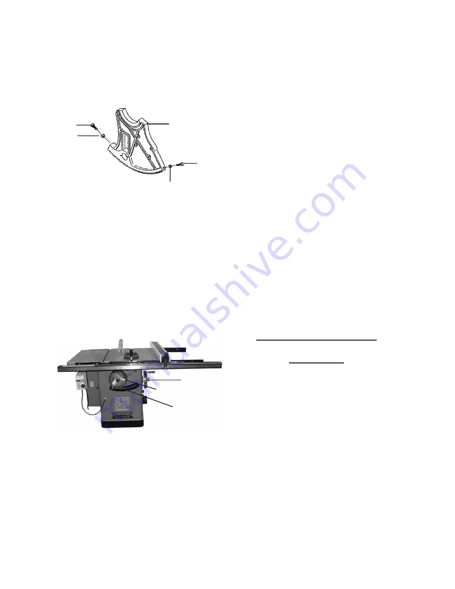
(See Figure r.)
FIgurE r
45°
STOp
BOLT
(254)
90°
STOp
BOLT
(254)
NuT
(253)
NuT
(253)
gEArEd TruNNION
(247)
2. Set the Saw Blade angle at zero as
shown on the Angle Scale (105) on
the front of the Table Saw, and raise
the Saw Blade to the maximum height
using the Blade Height Hand Wheel
(202).
(See Figure S.)
Set the Saw Blade at 90° to the Table
3.
(126) by turning the Blade Angle Hand
Wheel (202) clockwise as far as it will
go.
(See Figure S.)
BLAdE ANgLE HANd WHEEL
(202)
ANgLE SCALE
(105)
FIgurE S
BLAdE HEIgHT HANd WHEEL
(202)
4. Place a square on the Table (126) and
check to see that the Saw Blade is at
a 90° angle to the Table. Make sure
the square is touching the side of the
Saw Blade.
If the Saw Blade is not at 90° open
5.
the Motor Cover (114) to expose the
Geared Trunnion (247). Loosen the
Nut (253) on the Geared Trunnion,
and turn the Stop Bolt (254) in or
out. Back off both Stop Bolts one full
turn, then adjust them to achieve the
required blade angle. Tighten both
Stop Bolts until they both rest against
geared trunnion. Tighten the Nuts
(253). The Stop Bolt should stop
against left side Stopper Plate under
Table (126).
(See Figure r.)
Set the Saw Blade at 45° to the Table
6.
(126) by turning the Blade Angle
Hand Wheel (202) counterclockwise
as far as it will go.
(See Figure S.)
Place a square on the Table (126).
7.
If the Saw Blade is not 45°, loosen
the Nut (253) and turn the Stop Bolt
(254) in or out. Tighten the Nut (253).
(See Figure r.)
Check the accuracy of the Pointer on
8.
the Angle Scale (105) on the front of
the Table Saw. Adjust the Pointer if
necessary.
(See Figure S.)
To Adjust the Saw Blade
parallelism
This Table Saw will give the best
1.
results if the Miter (401 thru 419)
assembly is square to, and the Rip
Fence (1 thru 17) assembly are ad-
justed parallel to the Saw Blade. If
either assembly is not exactly parallel,
the saw cuts and finished work will
not be as precise. Also important, if
either assembly is not exactly in par-
allel the risk of kickback is increased.
To adjust the Saw Blade parallelism,
2.
raise the Blade Guard (301) up and
out of the way of the Saw Blade.
(See Figure A.)


