background image


30 


19.  To add an additional stage for the method, touch the “+” on the screen. 


20.  Repeat the above steps for each stage (5 maximum) of the method. 
 
21.  To edit the initial method parameters, select “Edit Method.” 
 
22.  To edit the parameters of a stage, select (touch and highlight) the appropriate stage. Select “Edit Stage 

Parameters.” 


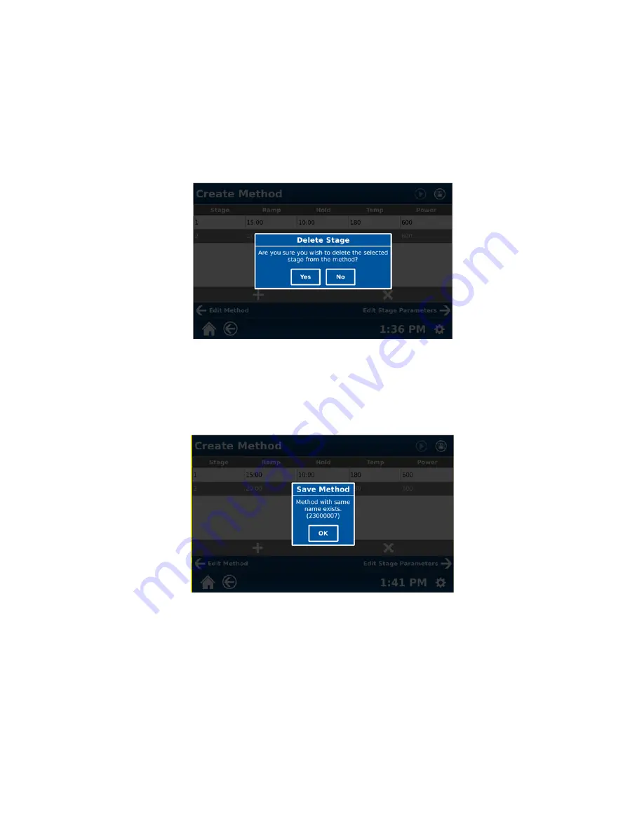
23.  To delete a stage, select (touch and highlight) the stage to delete and then select the “X” on the screen. 


24.  To delete the stage, select “Yes.” If the stage is not to be deleted, select “No.” 


25.  Once the method parameters are entered properly, the method can be saved by selecting the disk icon at the 

top of the screen. Once the method is saved, the disk icon will be grayed out. 


26.  If the method name is a duplicate, the following screen will appear. 


Summary of Contents for MARS 6

Page 1: ...Operation Manual Microwave Reaction System...

Page 2: ...ission from CEM Corporation CEM is a registered trademark of CEM Corporation One Touch Technology is a registered trademark of CEM Corporation One Touch PowerMAX DuoTemp EnergySeal SynergyPrep and The...

Page 3: ...ions that include high temperatures and pressures The use of vessels and vessel components other than original CEM parts will put operators and equipment at risk CEM will not assume any liability for...

Page 4: ...ssic Method 23 Edit Method 31 Review Method Information 32 Delete Method 34 Perform Method 34 Retrieve Data from Previous Method Performance 43 Selection of Single or Multiple Methods for Export and o...

Page 5: ...iv Ordering Information 92 Specifications 93 Warranty 95...

Page 6: ...nstrument cavity to perform a visual inspection If the instrument is suspected of interfering with the operation of a pacemaker the instrument should be turned off or the pacemaker wearer should move...

Page 7: ...nd an interlock monitoring system to prevent microwave emission when the door is open The MARS 6 uses microwave energy to heat samples Compounds such as water and other polar liquids absorb microwave...

Page 8: ...S 6 cavity is 10mL of acid or 50mL of water Microwave heating of alkaline or salt solutions in open or closed vessels will concentrate these solutions causing precipitation of salts and formation of c...

Page 9: ...orate etc Pyrophoric chemicals Hypergolic mixtures Nitric Acid and Phenol Nitric Acid and Triethylamine Nitric Acid and Acetone etc Animal Fats Esters of glycerol capable of nitration and the formatio...

Page 10: ...nt should be operated on stabilized constant voltage AC power supply Refer to Instrument Specifications in this manual Note Measure line voltage to ensure that it meets system specifications CAUTION L...

Page 11: ...ent cavity Install the elbow and exhaust hose on the back of the instrument Plug the power cord into the MARS 6 and the dedicated electrical outlet Verify that all accessories listed below have been i...

Page 12: ...7 10 Select the System Menu icon in the bottom right corner of the screen 11 Select Settings 12 Select System 13 Scroll the System screen to display Power...

Page 13: ...8...

Page 14: ...elect 230V 16 Select OK 17 Select the Save icon in the upper right corner of the screen to save the proper line voltage Note The MARS 6 instrument requires 208 230 VAC 60 Hz 15A 208 VAC or 220 240 VAC...

Page 15: ...GmbH Carl Friedrich Gauss Strasse 9 47475 Kamp Lintfort Germany 49 2842 96440 phone 49 2842 964411 fax info cem de email www cem de web site France Subsidiary CEM Wave S A S Immeuble Ariane Domaine Te...

Page 16: ...oor and engage the turntable Door Handle permits ease of opening instrument door Internal Printer Optional permits printing of method parameters graphs and or method data Waveguide Covers evenly distr...

Page 17: ...ug ESP 1500 Plus Connector Port Waveguide Cover ESP 1500 Plus Guide Block Floor Mat Inner IR Sensor Outer Vessel Counting Sensor Turntable Recognition Sensor Outer IR Sensor Inner Vessel Counting Sens...

Page 18: ...g Fan draws room air past the magnetron Power Cord Receptacle receives the female end of the power cord Fuses prevent electrical power overload External Sensor Port permits interface of optional instr...

Page 19: ...instrument cavity If the instrument is suspected of interfering with the operation of a pacemaker the instrument should be turned off or the pacemaker wearer should move away from the instrument Stan...

Page 20: ...th certain vessel sets With this system two infrared temperature sensors are located below the cavity floor ReactiGuard Cavity Sensing System The MARS 6 is equipped with an audible sensing system to d...

Page 21: ...e use of DuoTemp control for EasyPrep EasyPrep Plus and MARS Xpress Plus vessel sets This feature utilizes the infrared sensor and the MTS 300 fiber optic sensor to control the hottest vessel in any m...

Page 22: ...inter Faxes and scanners are not supported by the MARS 6 5 Follow the instructions on the screen to select a printer driver and install it 6 Once the install is completed immediately select Print Test...

Page 23: ...isplay Numbers Alt Shift Display Symbols Backspace Delete Hide Keyboard Subscript Methods created by the CEM Corporation Laboratory are displayed with a CEM folder Methods created by a current operato...

Page 24: ...r all major sample types One Touch Methods can also be created and saved by the user Instructions for creating a One Touch method are included in this manual Classic methods are created by the user In...

Page 25: ...type vessel type and sample type for some vessels as well as temperature and pressure control options Note Throughout the text of this manual the word select is used to indicate touch 1 From the MARS...

Page 26: ...b key Use the backspace del delete key to delete unwanted letters and or numbers Use the space bar to enter a space in the method name Once the name is properly selected and displayed select Hide to c...

Page 27: ...tes for the method Note To toggle between upper and lower case letters for the notes select the shift key on the keypad To toggle to numbers and symbols for the notes select alt on the bottom of the k...

Page 28: ...Once the method parameters are entered properly the MARS 6 will complete all other necessary information to perform the method with one touch 18 Save the method by selecting the disk icon at the top...

Page 29: ...thod control type vessel type and sample type for some vessels as well as temperature and pressure control options Note Throughout the text of this manual the word select is used to indicate touch 1 F...

Page 30: ...d name select alt on the bottom of the keypad To use a subscript select the sub key Use the backspace del delete key to delete unwanted letters and or numbers Use the space bar to enter a space in the...

Page 31: ...vessel choices based on the selected control type to choose the desired vessel Note If Evaporation is selected as the control type in step 6 above selection of vessel type will not be applicable Proc...

Page 32: ...the notes select the shift key on the keypad To toggle to numbers and symbols for the notes select alt on the bottom of the keypad Use the backspace del delete key to delete unwanted letters and or nu...

Page 33: ...d as illustrated in the screens below Note If Evaporation is selected as the control mechanism the Pressure column will be replaced by a programmable temperature delta as illustrated in the above scre...

Page 34: ...S Xpress Vessels 800 watts 3 6 Framed Vessels 800 watts 13 20 MARS Xpress Vessels 1200 watts 7 12 Framed Vessels 1600 watts 21 40 MARS Xpress Vessels 1800 watts Note Based on the vessel type chosen fo...

Page 35: ...te stage Select Edit Stage Parameters 23 To delete a stage select touch and highlight the stage to delete and then select the X on the screen 24 To delete the stage select Yes If the stage is not to b...

Page 36: ...31 27 Select OK to return to the following screen 28 Select Edit Method 29 Select Name and rename and save the method using the instructions outlined...

Page 37: ...om the MARS 6 home screen select Classic Methods 2 Scroll through the methods until the desired method is visible Touch and hold long touch the method to be edited 3 Select the edit icon pencil at the...

Page 38: ...f the screen to save the edited method CAUTION When a method is edited and saved the original method is no longer available in the instrument memory Review Method Information 1 From the MARS 6 home sc...

Page 39: ...34 4 Scroll the Method Information screen to view the remainder of the method information as illustrated below...

Page 40: ...rough the methods until the desired method is visible Touch and hold long touch the method to be deleted 2 Select touch the X icon at the top of the screen The following screen will appear 3 Select Ye...

Page 41: ...e reagent ReactiGuard alerts the operator to the occurrence of an event within a vessel therefore CEM recommends that ReactiGuard be on at all times Use extreme caution while attempting to identify th...

Page 42: ...ith the operation of a pacemaker the instrument should be turned off or the pacemaker wearer should move away from the instrument 4 Install the turntable into the instrument ensuring that the flat edg...

Page 43: ...ly be purchased direct from CEM or through its authorized dealer network CEM vessels are covered by worldwide patents including US patents 8 480 981 and 6 136 276 7 If the vessel set has a retaining r...

Page 44: ...cooling etc MTS 300 Temperature Control 12 If the instrument door is not properly closed or is opened during performance of a method the following screen will be displayed 13 Ensure that the door is p...

Page 45: ...red Control Ramping to Specified Temperature Holding at Specified Temperature 14 If Pause is selected during performance of a method the following screen will be displayed 15 Select Continue to resume...

Page 46: ...een or the applicable icon on the right side of the screen 17 To print the method information displayed on the screen using the optional internal printer at any time during the method performance sele...

Page 47: ...42 Power Time Graph Temperature Time Graph Temperature in Vessel Graph...

Page 48: ...ed to the post method cool down operation if it is turned on in the system setup procedure WARNING CEM Corporation recommends that a post method cool down time be used for each digestion performed in...

Page 49: ...ct Classic Methods or One Touch Methods 2 Scroll through the methods until the desired method is visible Touch and hold long touch the method from which the data is to be used 3 Select touch the Scree...

Page 50: ...Run Data 5 Scroll through the method run data screen to view all available information If the instrument is equipped with a printer select the print icon at top of the screen to print any of the run...

Page 51: ...s for Export and or Deletion Export Single Multiple Methods 1 From the MARS 6 home screen select Classic Methods or One Touch Methods 2 Scroll through the methods until the first desired method is vis...

Page 52: ...If a single method is to be exported or deleted select touch Single Select The last method selected will be the only method to remain selected 5 Select touch the previous method selected in step 3 6 S...

Page 53: ...od DeleteSingle Multiple Methods 11 Follow steps 1 through 10 above 12 Select the X delete icon at the top of the screen to delete the method s To export the method s follow steps 8 through 10 above P...

Page 54: ...erformed in step 4 6 Touch the Screen Context Menu icon 7 Select View Run Data 8 Select the date and time of the method tested Scroll the View Run Data screen upward to display Sample Information 9 To...

Page 55: ...h and scroll through the System information to view Status and Service Dates NOTE The System screen provides instrument information including temperature and pressure readings door status open or clos...

Page 56: ...will turn on Select Off to stop the test To turn the cavity lights on or off toggle the On or Off selection 5 Select Power 6 The Power selection is used to perform a manual power test Refer to Microw...

Page 57: ...libration of the IR sensors 9 Select Pressure 10 The Pressure tool is provided for calibration of the pressure device Refer to Pressure Calibration in the Maintenance Troubleshooting and Service secti...

Page 58: ...er of the screen to select options for display of the activity log 13 To select a user rather than an administrator select Administrator 14 Select either All Users Administrator or a specific user Onc...

Page 59: ...screen 19 Select Update Manager 20 Install a USB flash drive into one of the USB ports 21 Select Select Update 22 Select highlight the software version to be installed 23 Select OK 24 Select Install T...

Page 60: ...t touch the System Menu icon in the bottom right corner of the screen 26 Select Settings 27 Select General The above screen provides legal system information including the instrument serial number the...

Page 61: ...revised only by a CEM Certified Service Engineer 29 Select Contact Us for CEM contact information 30 Select Legal Notice for the copyright information pertaining to the software installed in the instr...

Page 62: ...ment can be idle prior to the screen saver appearing on the screen Screen saver time can be set from 1 to 120 minutes in increments of 5 Default screen saver time is 5 minutes To adjust the screen sav...

Page 63: ...58 39 Scroll the System screen to display Power 40 Select Line Voltage 41 Select and highlight the proper voltage for the instrument 208V or 230V 42 Select OK 43 Select Localization...

Page 64: ...sired language 46 Select OK 47 Select Date Format 48 To display the available date formats select the drop down menu by touching the displayed date format 49 Select the desired method for displaying t...

Page 65: ...parameters are selected touch the disk icon at the top of the screen to save the selected parameters Once the parameters are saved the disk icon will be grayed out 58 Select Date Tiime 59 If the date...

Page 66: ...at the top of the screen Once the date and time are saved the disk icon will be grayed out 66 Select Users 67 Note If the auto login is turned on the first screen shown below will appear If the auto l...

Page 67: ...lect touch Enter current password 70 Using the keypad enter the current administrator or user password 71 Once the current password is entered select hide to close the keypad 72 Select OK 73 If the pa...

Page 68: ...password has been entered correctly the Reset Password screen will appear as illustrated above in step 72 Using the keyboard enter the new password 77 Select OK 78 Using the keyboard enter the new pas...

Page 69: ...o add a new user select Add User 81 Select User Name 82 Using the keypad enter the appropriate user name Once the user name is entered select hide to close the keypad 83 Select the arrow beside Select...

Page 70: ...85 Select OK to return to the Users screen 86 Select Password 87 Using the keypad enter the user password 88 Select hide to close the keypad 89 Select Confirm Password 90 Using the keypad enter the u...

Page 71: ...y select Add to add the user to the instrument software 93 To edit a user s information select the edit icon for the user 94 Edit the user s information as outlined above for adding a user 95 To delet...

Page 72: ...Select Run Based on the setting for the Data Output one of the two following screens will appear 98 Data output can be sent to a PC or USB flash drive Select On or Off for data output 99 Select Mode...

Page 73: ...screen upward to display the selections for Data Report 105 Select On or Off for the items to be included in the data report Temperature Sample ID Description Reagents Mass and Volume 106 Once the it...

Page 74: ...107 Scroll the Run screen upward to display Data Interval Mode and Door Lock 108 Select the Data Interval Time 5 to 60 seconds in increments of 5 109 Select OK 110 Select the Cool Down Mode 111 Select...

Page 75: ...in increments of 5 Default cool down time is 15 minutes 113 Select OK 114 If the instrument is equipped with the door lock assembly option toggle the Door Lock On or Off 115 Scroll the Run screen upwa...

Page 76: ...etection sensors recognize the type and number of vessels that have been placed in the instrument cavity Note Audio status indicator is an audible chime between stages of a method and at the end of a...

Page 77: ...10 degree increments etc 124 Select the appropriate temperature parameter increment 1 5 or 10 125 Select OK 126 Select Power Note The power increments are 10 25 50 or 100 If thepower parameter increm...

Page 78: ...entered select GF Number 132 Using the keyboard enter the GF Number of the fiber optic probe installed in the instrument Once the number is properly entered select hide to close the keyboard 133 To c...

Page 79: ...ure of the water Record the measured temperature on the thermometer 137 Select the Reference Temperature 138 Using the keyboard enter the temperature of the fiber optic probe measured and recorded 139...

Page 80: ...nsor setting screen to reveal IR and Pressure information Note The IR and Pressure sections of the Sensors screen provide the IR sensor s and pressure calibrations Refer to the calibration documentati...

Page 81: ...int a test page to ensure that the optional internal printer is operating properly 146 Select Networking to display the IP address of the instrument 147 From the MARS 6 home screen select the System M...

Page 82: ...2 During the video select Stop to stop the video or Pause to pause it 153 To adjust the volume of the video touch and move the slider upward to increase the volume or downward to decrease the volume N...

Page 83: ...leaning Weekly Clean and dry Omni Xpress Easy Prep Easy Prep Plus and open vessels Weekly When using vessel types other than Omni Xpress Easy Prep Easy Prep Plus or open vessels wipe the cavity with w...

Page 84: ...into the ESP Microwave Leakage Measurement 1 The door and cavity are very durable and are designed for reliable operation under severe laboratory conditions External radiation checks are performed on...

Page 85: ...y sensitivity to properly test an instrument for microwave leakage The U S Government defines excessive microwave leakage as 5 mW cm2 If the instrument shows excessive microwave leakage do not attempt...

Page 86: ...tron s for performing the power test Primary Secondary or Both 7 Select Both 8 Select OK 9 Select Power 10 Select the desired percentage of power to be used for the power test 0 100 in increments of 5...

Page 87: ...t is calculated as follows Power in Watts 47 Tf Ti 18 If the measured power is below 1600W repeat the microwave power measurement If the power remains less than 1600W the instrument is not producing a...

Page 88: ...C 1 The instrument must be plugged into an electrical outlet and turned on 2 Remove the plastic floor mat from the floor of the instrument 3 Plug the Intelli Temp calibrator into an electrical outlet...

Page 89: ...84 6 Select IR to perform an IR sensor calibration 7 Select Sensor 8 Select the sensor Inner or Outer to calibrate 9 Select OK 10 Select Target C...

Page 90: ...down with the opening mating with the opening of the adaptor 15 Press Start Wait for a stable reading 16 Repeat the above steps to calibrate the second sensor Verification of IR Sensor s Calibration...

Page 91: ...with the calibrator support ring positioned directly over the sensor being calibrated Place the Intelli Temp calibrator over the adaptor calibrator positioned upsode down with the opening mating with...

Page 92: ...the product tag cannot be located contact the CEM Corporation Synthesis Department at 800 726 3331 or 704 821 7015 2 Log into the CEM website www cem com 3 Select the applicable instrument model from...

Page 93: ...ager 12 If any update s is available select the firmware version to download from the Available area of the above screen 13 Press Install CAUTION Firmware update requires approximately 10 20 minutes f...

Page 94: ...adjusted Faulty interlock s Fuse Blows Repeatedly During Operation Low line voltage Faulty high voltage component Faulty DC power supply Faulty controller board Inoperative Turntable Faulty turntable...

Page 95: ...owave energy Liquid does not generate pressure upon heating Vessels improperly torqued No Rise in Temperature in Control Vessel Sample does not absorb microwave energy Temperature probe inserted incor...

Page 96: ...in the high voltage section or area bridge the contacts of the high voltage capacitors using the metal shaft of a well insulated screwdriver to discharge the residual voltage in the capacitors This wi...

Page 97: ...aine Technologique de Saclay 4 rue Ren Razel 91892 ORSAY Cedax France 33 1 69 35 57 80 phone info fr cem com email Ireland Subsidiary CEM Ireland Sky Business Centre 9a Plato Business Park Demastown D...

Page 98: ...Heavy duty multi layer Teflon coating Electrical Requirements 208 230 VAC 207 253 VAC 60 HZ 15A 208 VAC 220 240 VAC 202 250 VAC 50 Hz 15A 220 VAC Magnetron Frequency 2450 MHz Power Output 1800 watts...

Page 99: ...ientific and Medical Equipment US Safety Approval to UL61010 1 ETL Testing Laboratories Canadian Safety Approval to CAN CSA C22 2 No 61010 1 European Community and Remainder of the World Conforms to E...

Page 100: ...rument as required How to Get Service Purchaser should contact the Service Department of CEM Corporation or the nearest CEM subsidiary or distributor for return authorization and for proper crating an...

Page 101: ...tion Service Department PO Box 200 3100 Smith Farm Road Matthews NC 28106 0200 USA 800 726 5551 phone within USA 01 704 821 7015 phone outside of US 01 704 821 4369 fax service cem com email www cem c...

Reviews: