background image

Attention !

Default port of Industrial Automation (Modbus Gateway) is 502.

If on the local network conflict with other network service using the same port, change number of port into another for the

service server of serial bridge and client in the server  port configuration.
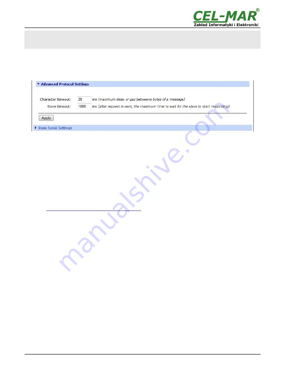
On section 

Advanced Protocol Settings

 (fig. below),  set the timeout by entry:

Character timeout

 - value in ms., maximum delay or gap betweens bytes of a message – default 20 ms.

Message timeout 

- value in ms., maximum delay or gap betweens bytes of a message – default 2500ms; this time 

must not

 be 

less than the timeout set on MODBUS MASTER devices / SCADA/HMI software.

For saving the 

Advanced Protocol Settings

 press [

Apply

].

Fig. 32. Example configuration for communication with  MODBUS-SLAVE devices – configuration of timeout parameters for

SLAVE type device

5.2.2.1.5.3. SERIAL PORT TRANSMISSION PARAMETERS

For proper operation of ADA-14040 with device connected to his serial port, should be set the same transmission parameters for both
devices. Select  

Basic Serial Settings  

and enter  

Baud Rate

,  

Data Bits

,  

Parity

,  

Stop Bits,

  the same parameter like has device

connected to the Wireless Serial Server.

5.2.3. SYSTEM SETTINGS

Select on left panel menu  

Configuration -> System 

and then on right will be selections as follow:

Device Identity Settings - 

allows to add name of the wireless serial server, describe the location and add identification number,

Simple Network Managment Protocol Setings (SNMP) - 

 allows to make the configuration of management protocol SNMP.

5.2.4. USERS CONFIGURATION

On the configuration page 

Users

 are two sections:

Users

 - allows to configure the method of login to ADA-14040. Selecting the option  

Enable user logins 

means that after enter the

address 

http://<adres-ip-konwertera>/admin/administration.htm

 to internet browser, will open login window and will be necessary to

enter user name and password.

Configure Users

 - allows to add additional user, change password, configure access and permissions for each defined users.

5.2.4.1. CHANGING USER MANE AND PASSWORD 

Changing the default user 

root

 and password, can be done as follow :

1. press user mane 

root

 in section 

Users Configuration->Configure Users,


2. enter new user name and password. 
3. press [

Apply

] for saving.

5.2.4.2. ADDING NEW USER WITH LIMITED PERMISSIONS ASSOCIATED 

For adding new user with limited permissions for configuration or management follow the steps below:
1. From menu 

Configuration 

select 

Users,

2. In section 

Configure Users, 

press

 [New...]

,

3. Enter user mane (eg. 

admin

) and password – twice, and press 

[Apply]

,

4. Will open the page 

Users Configuration

, where in section 

Configure Users

, will be new user name.

Now it is possible to configure access permissions to the wireless serial server, and permissions for configuration of this new user.

Configuration of access to the wireless serial server:
1. From menu 

Configuration 

select 

Users,

2. In section 

Configure Users

, select added user eg. 

admin

,

3. Will open the page  

User Configuration

 – admin, where are sections:

A/ 

User Configuration 

– possibility of rename user and password,

B/ 

User Access

 - method of access to the wireless serial server from the network:

Allow command line access

 – access using the Command Line Interface - 

telnet

,

Allow web interface access

 – access using the internet browser. 

C/ 

User  Permissions - 

user permissions to configuration and management of the ADA-14040, where are an options:

None

 - no permission,

Read - 

permission to read,

Read Self - 

permission to read own settings, but not other users.

Read/Write 

- full permission to read and write the setting.

Read/Write Self - 

permission to read and write own setting, but not other users.

26

ADA-14040

Summary of Contents for ADA-14040

Page 1: ...User manual ADA 14040 RS 485 RS 422 to Wi Fi 802 11b Wireless Serial Server with MODBUS GATEWAY 1 io_ada 14040mg_v1 17_en ADA 14040 Copyright 2001 2017 CEL MAR sp j...

Page 2: ...ACTIVATION 12 5 CONFIGURATION 13 5 1 INITIAL CONFIGURATION USING ADAFINDER SOFTWARE 13 5 1 1 ADAFINDER INSTALLATION 13 5 1 2 NETWORK SETTING 13 5 2 CONFIGURATION AND MANAGEMENT WITH USE OF INTERNET BR...

Page 3: ...5 2 6 3 UPDATE FIRMWARE 27 5 2 6 4 FACTORY DEFAULT SETTINGS 27 5 2 6 5 SYSTEM INFORMATION 27 5 2 6 6 REBOOT 27 5 2 6 7 LOGOUT ENDING THE MANAGEMENT 27 6 USING VIRTUAL PORT SERVICE REALPORT 27 6 1 VIRT...

Page 4: ...supply network is only after disconnecting the power supply circuit voltage Do not carry out the assembly or dis assembly of the device if it is enabled This may result to short circuit and damage th...

Page 5: ...ls such as RX RX TX A TX B Can be connected 32 devices to RS485 Bus created on the base ADA 14040 operate in half duplex or full duplex mode on 4 wire RS485 Bus It is adapted to supply an external vol...

Page 6: ...n one end of the cable lay signal cables at a distance not less than 25 cm from power cables use suitable diameter cable for power supply on account of voltage drop use the interference eliminators fo...

Page 7: ...HCP server to change IP address should be used ADAFinder software see p 5 1 Details of the connection to wireless network will be described in the bellow chapters 3 2 1 CONNECTION TO PC BY THE USE OF...

Page 8: ...in virtual serial port mode RealPort or TCP UDP sockets Fig 6 Connection to functioning in virtual serial port mode RealPort or TCP UDP sockets via INTERNET 8 ADA 14040 ADA 14040 Wi Fi ROUTER or ACCES...

Page 9: ...ection to functioning in TCP or UDP serial bridge mode via INTERNET network 9 ADA 14040 RS485 bus RS485 bus ADA 14040 static IP address Wireless network 802 11b g connection Ad Hoc type between ADA 14...

Page 10: ...on MODBUS TCP with MODBUS RTU ASCII in one network by the use ADA 14040 with MODBUS Gateway 10 ADA 14040 RS485 bus RS485 bus RS485 Urz dzenie z interfejsem RS232 MASTER device ADA 14040 static IP addr...

Page 11: ...4 wire RS485 Bus should be set the MODE switch on the front panel of ADA 14040 in RS485 mode Connect wires of bus to terminals TX A TX B RX RX like below Fig 12 Example connection of device with RS485...

Page 12: ...W1 2 ON connection Line Termination 120 W to terminals Rx Rx OFF disconnection Line Termination 120 W from terminals Rx Rx 3 4 POWER SUPPLY CONNECTION The power supply to the ADA 14040 should be DC re...

Page 13: ...is searching local network LAN WLAN and if find the ADA 14040 will add them to the list of available port servers Devices Fig 14 To change the network setting of ADA 14040 should select the converter...

Page 14: ...Fig 14 Base configuration network by the use ADAFinder software Fig 15 View of ADAFinder configuring IP address window 14 ADA 14040...

Page 15: ...ser For configuration open the Internet Browser and type the address http converter ip address admin administration htm The login windows will open Enter User name and Password as follow Username root...

Page 16: ...will reduce settings of channels to the list of legally defined for the country From list Channel select the channel on which the server will operate Selection the Auto Scan from list will cause sear...

Page 17: ...on of ADA 14040 select on left panel Configuration Network and then on right Socket Tunnel Settings This section is used to connect two network devices one on the ADA 14040 RS485 RS422 to Wi Fi Wirele...

Page 18: ...not taken what will cause the error message 5 2 2 1 2 TCP SOCKETS Choosing TCP Sockets is configured the serial port of ADA 14040 server for communication with PC by the use of TCP socked Data sendin...

Page 19: ...tion between server and client even if the data is not transmitted over the network and reconnection in case of interruption Configuration of this option can be made by selection Configuration Network...

Page 20: ...Settings with operating parameters like on picture below Set an access to UDP server on e g 2101 port Then select Automatically send serial data in section UDP Client Settings this automatically send...

Page 21: ...ns is recommended to set parameters like on picture bellow For saving the configuration of UDP client and server for SLAVE device press Apply Fig 22 Example configuration of ADA 14040 UDP server clien...

Page 22: ...transmission parameters for both devices Select Basic Serial Settings and enter Baud Rate Data Bits Parity Stop Bits the same parameter like has device connected to the Wireless Serial Server 5 2 2 1...

Page 23: ...for communication with MODBUS MASTER devices type of device and protocol In section Destination Settings fig below set the options of inquires from Master device to Slave device in fields Host name en...

Page 24: ...and MASTER MODBUS RTU devices For saving the Advanced Protocol Settings press Apply Fig 28 Example configuration for communication with MODBUS MASTER devices setting of Timeouts 5 2 2 1 5 2 CONFIGURAT...

Page 25: ...ings eg as on picture below Press Apply for saving configuration Fig 30 Example configuration for communication with MODBUS SLAVE Go to section Modbus TCP Network Settings Global configuration options...

Page 26: ...r the address http adres ip konwertera admin administration htm to internet browser will open login window and will be necessary to enter user name and password Configure Users allows to add additiona...

Page 27: ...6 3 UPDATE FIRMWARE Section Update Firmware enables to make the update firmware form the file Firstly should be done update the POST before updating the firmware more details available after contact w...

Page 28: ...alling COM port No Ports Starting COM and press Finish The driver will be installed In this way installed virtual port can require the configuration in case of connecting the wireless serial server to...

Page 29: ...Fig 33 Devices view on Windows XP Fig 34 Example configuration of multi port serial adapter 29 ADA 14040...

Page 30: ...searching restore Default Settings according to steps below 1 Power OFF the ADA 14040 2 Remove the cover of Serial Server Wi Fi connector 3 Press RESET RST and holding the button turn the power on of...

Page 31: ...rences STP Nx2x0 5 24AWG Transmission type Asynchronous full duplex half duplex Optical Signalization PWD green LED power supply RX red LED data receiving on RS485 RS422 TX yellow LED data transmissio...

Page 32: ...mmunications products in the world such as data transmission converters with interface RS232 RS485 RS422 USB Ethernet Wi Fi Current Loop Fibre Optic Converters and other Please contact us to tell how...

Reviews: