5.2.2.1.2.3. SERIAL PORT TRANSMISSION PARAMETERS
For proper operation of ADA-14040 with device connected to his serial port, should be set the same transmission parameters for both
devices.
Select
Basic Serial Settings
and enter
Baud Rate
,
Data Bits
,
Parity
,
Stop Bits,
the same parameter like has device connected to
the Wireless Serial Server.
5.2.2.1.3. UDP SOCKETS
Choosing
UDP Sockets
is configured the serial port of ADA-14040 server, for direct communication with PC or other device
connected to the network by the use of TCP socked. Data sending by application or other device/s to this port are transferred through
WLAN/WAN to ADA-14040 server and are present on his serial port. Press [
Apply
] for save.
5.2.2.1.3.1. UDP CLIENT & SERVER CONFIGURATION IN CASE OF MASTER DEVICE
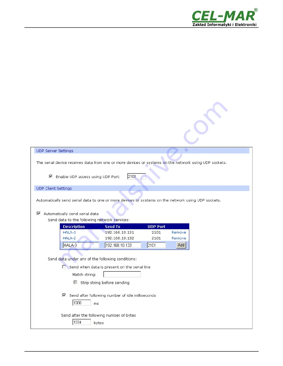
After saving the UDP Sockets profile, will open section
UDP Server Settings
with operating parameters like on picture below. Set an
access to UDP server on e.g. 2101 port. Then select
Automatically send serial data
in section
UDP Client Settings
, this
automatically send received data by the use UDP client service to the SLAVE device connected to LAN/WAN through e.g. ADA-
13020, ADA-13028L, ADA-13040, ADA-13110, ADA-14040.
On lists
Send data to the following network services
are addresses of network devices and ports to which will be send data. In
field:
-
Description
- enter e.g. location of the converter and SLAVE device,
-
Send To
- enter IP address of e.g. converter, connected to SLAVE device,
-
UDP Port
- enter the number of port on which is working UDP Server of converter connected to SLAVE device and press
[Add]
In the section
Send data under any of the following conditions
is recommended to set parameters like on picture bellow.
For saving the configuration of UDP client and server for MASTER device, press
[Apply]
.
Fig 21. Example configuration of ADA-14040 UDP server&client connected to MASTER device
20
ADA-14040