


Operation Manual
Safe2+ / Safe4
©
CEDES
Safety & Automation AG / June 2008
www.cedes.com 15
Danger
The safety devices and the interconnection to
the machinery have to comply with the basic
safety requirements as mentioned in the cur-
rent regulations and standards.
Direct interfacing of a safety light curtain to
machine control that does not meet the neces-
sary safety integrity level, i.e. use of general
purpose PLCs or general purpose relays can
cause serious injury or death of persons.
Consult a professional safety engineer!
Danger
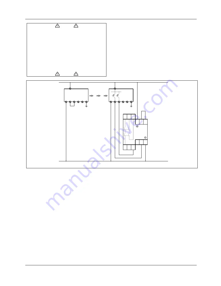
0 VDC
+24 VDC
Safe4
Sender/
Emitter
Safe4
Empfänger
Receiver
1
2
3
4
5
6
7
1
2
4
5
6
7
3
13 23 24
CEDES
SafeC S
14
S11 S12
A1
S33 S34
S21 S22
A2
Figure 21: Diagram for automatic reset mode with CEDES SafeC S (Part No: 103 105)