


IMS 100
Installation and Operation Manual
4
www.cedes.com
© CEDES/April 2014
2
2..
D
De
elliivve
erryy cco
on
ntte
en
ntt
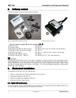
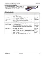
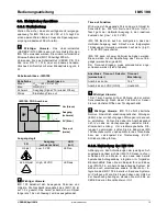
The IMS 100 system consists of the following components:
Figure 1: Typical IMS 100 system components
Figure 2: Power line converter
Parts information for typical IMS system components
-
IMS 100 sensor
P/N 106 834
Connection cable
P/N 104 153
Mounting bracket IMS 100, flush mounting
P/N 106 852 (30°) or P/N 113 236 (35°); model dependent
Mounting box IMS 100, surface mounting
P/N 108 176
IMS 100 accessories kit
P/N 108 177, comprises 4 clips, 2 screws, reflective tape
Installation and operation manual
P/N 106 854
Power line converter 85 …265 VAC
P/N 106 666 or P/N 111 014; model dependent
Important:
Integrating the CEDES IMS 100 sensor into a new or existing door protection system can be accomplished in sever-
al ways depending on the elevator control system requirements. The following sections provide examples for incor-
porating the IMS 100 into an existing system. The contents of each delivery depend on the system ordered. Should
you have any queries regarding the contents of this delivery, or if you require application assistance, please contact
CEDES or your local distributor.
3
3..
M
Me
ecch
ha
an
niicca
all iin
nsstta
alllla
attiio
on
n
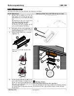
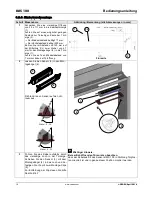
The installation should be done in the following order:
1. Switch off power and mark clearly that this elevator is out of service
2. Mechanical installation of the IMS 100
3. Electrical installation and integration of IMS 100
4. Power-up and test for proper function
3
3..1
1..
SSw
wiittcch
h O
OFFFF m
ma
aiin
n p
po
ow
we
err
For your own safety, turn the power off before you start working on the elevator! Clearly mark that this elevator is out
of service. Keep the working area closed to the public all the times.
7
1
3
4
6
2
5


