— 28 —
4
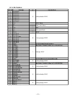
-10. FRO
M
(IC2
4:
M
B
M
29F160BE90TN)
4
-10-1. Pin Assi
g
nment
1
2
3
4
5
6
7
8
9
10
11
12
13
14
15
16
17
18
19
20
21
22
23
24
BYTE
VSS
DQ15/A-1
DQ7
DQ14
DQ6
DQ13
DQ5
DQ12
DQ4
VCC
DQ11
DQ3
DQ10
DQ2
DQ9
DQ1
DQ8
DQ0
OE
VSS
CE
A0
48
47
46
45
44
43
42
41
40
39
38
37
36
35
34
33
32
31
30
29
28
27
26
25
A15
A16
A14
A13
A12
A11
A10
A9
A8
A19
N.C.
WE
RESET
N.C.
WP
RY/BY
A18
A17
A7
A6
A5
A4
A3
A2
A1
4
-10-2. Pin F
u
nction
A
-1
V
SS
V
CC
WE
CE
A
0
to A
18
OE
DQ
0
to DQ
15
BYTE
RESET
STB
STB
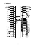
Erase Voltage
Generator
State
Control
Command
Register
Program Voltage
Generator
Input/Output
Buffers
Data Latch
Chip Enable
Output Enable
Logic
Low V
CC
Detector
Timer for
Program/Erase
Address
Latch
Y-Decoder
X-Decoder
Y-Gating
Cell Matrix
RY/BY
RY/BY
Buffer
Pin
F
u
nction
A
-1
, A
0
to A
19
Address Inputs
DQ
0
to DQ
15
Data Inputs/Outputs
CE
Chip Enable
OE
Output Enable
WE
Write Enable
RY/BY
Ready/Busy Output
RESET
Hardware Reset Pin/Temporary Sector Unprotection
BYTE
Selects 8-bit or 16-bit mode
N.C.
No Internal Connection
V
SS
Device Ground
V
CC
Device Power Supply
4
-10-3. Block Dia
g
ram
Summary of Contents for TE-2200
Page 16: ... 14 DRAWER 35 Remove the case 36 Remove 10 screws 37 Remove the DARWER cable ...
Page 22: ... 20 4 5 DRAWER I F CIRCUIT The drawer open circuit is as follows ...
Page 23: ... 21 4 6 PRINTER CONTROL CIRCUIT The printer control circuit is as follows ...
Page 68: ... 66 8 PCB LAYOUT MAIN PCB E466 1 PCB TOP VIEW ...
Page 69: ... 67 MAIN PCB E466 1 PCB BOTTOM VIEW ...
Page 93: ... 91 TE 2400 KEYBOARD BLOCK 16 15 17 18 19 20 21 22 23 ...
Page 98: ... 96 11 DRAWER DL 2429 for USA 16 17 18 11 8 6 15 14 19 9 10 1 12 20 21 5 4 2 3 5 13 7 ...
Page 104: ... 102 14 DRAWER DL 2799 for UK Canada 12 17 11 8 7 6 9 10 1 18 19 5 4 2 5 16 13 15 14 3 ...


