— 34 —
[
4
] RA
M
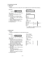
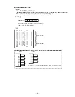
READ ONLY test
[Function]
RAM READ ONLY test is performed.
Perform the WRITE test (n011) right before start of this test.
System area test for COMMON is not performed.
[Operation]
Operation :
n
1
1
1
SUBTOTAL
n : 0
= One time check (can be omitted)
not 0 = Continuous check ( Press the “C” key or turn off the power by rotating the key to
end the test.)
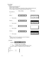
[Pop-up display]
A counter is displayed for Pop-up display.
Address of an error is printed if the test ended with an error.
n=0
1
2
3
[Main display]
n
D I A G
0 1 1 1
0 0 n
n=0
1
2
3
[Print]
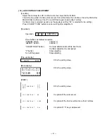
The result for all area test for RAM is printed as follows.
* Refer to RAM WRITE/READ test when NG is printed.
R A M
1 1 1
R A M
R D
O K
E N D
1 1 1
[
5
] CF-CARD WRITE/READ test
[Function]
This test will check the write/read test (connection test) for CF-CARD.
Perform the CF-CARD clear test, before start of this test.
Note that this test does not ensure the data inside the CF-CARD as well as its performance.
[Operation]
Operation :
0
n
0
1
3
SUBTOTAL
n : 0
= One time check( can be omitted)
not 0 = Continuous check (To stop the test, press “C” key or turn off the power by rotating
the key.)
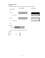
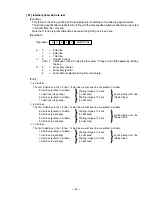
[PRINT]
NG and the address are printed if WRITE cannot be done
normally.
C F - C A R D
1 3
C F
W R
O K
E N D
1 3
Summary of Contents for TE-2200
Page 16: ... 14 DRAWER 35 Remove the case 36 Remove 10 screws 37 Remove the DARWER cable ...
Page 22: ... 20 4 5 DRAWER I F CIRCUIT The drawer open circuit is as follows ...
Page 23: ... 21 4 6 PRINTER CONTROL CIRCUIT The printer control circuit is as follows ...
Page 68: ... 66 8 PCB LAYOUT MAIN PCB E466 1 PCB TOP VIEW ...
Page 69: ... 67 MAIN PCB E466 1 PCB BOTTOM VIEW ...
Page 93: ... 91 TE 2400 KEYBOARD BLOCK 16 15 17 18 19 20 21 22 23 ...
Page 98: ... 96 11 DRAWER DL 2429 for USA 16 17 18 11 8 6 15 14 19 9 10 1 12 20 21 5 4 2 3 5 13 7 ...
Page 104: ... 102 14 DRAWER DL 2799 for UK Canada 12 17 11 8 7 6 9 10 1 18 19 5 4 2 5 16 13 15 14 3 ...


