— 24 —
4
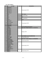
-7-3. Pin F
u
nction
PIN NO.
PIN NAME
I/O
DESCRIPTION
1
P120/RTP0
2
P121/RTP1
3
P122/RTP2
4
P123/RTP3
5
P124/RTP4
6
P125/RTP5
7
P126/RTP6
8
P127/RTP7
9
VDD
-
Power Supply
10
X2
-
11
X1
I
12
VSS
-
GND
13
XT2
-
14
XT1
I
15
RESET
I
Reset
16
P00/INTP0
17
P01/INTP1
18
P02/INTP2/NMI
19
P03/INTP3
20
P04/INTP4
21
P05/INTP5
22
P06/INTP6
23
AVDD
-
A/D CONVERTER POWER SUPPLY
24
AVREF0
-
Application of Standard Voltage for A/D CONVERTER
25
P10/ANI0
26
P11/ANI1
27
P12/ANI2
28
P13/ANI3
29
P14/ANI4
30
P15/ANI5
31
P16/ANI6
32
P17/ANI7
33
AVSS
A/D CONVERTER & D/A CONVERTER GND
34
P130/ANO0
35
P131/ANO1
36
AVREF1
Application of Standard Voltage for D/A CONVERTER
37
P70/RxD2/SI2
38
P71/TxD2/SO2
39
P72/ASCK2/SCK2
40
P20/RxD1/SI1
41
P21/TxD1/SO1
42
P22/ASCK1/SCK1
43
P23/PCL
44
P24/BUZ
45
P25/SI0/SDA0
46
P26/SO0
47
P27/SCK0/SCL0
48
P80/A0
49
P81/A1
50
P82/A2
8 bit input/output PORT
Main system Clock
Sub system Clock
IO
IO
7 bit input/output PORT
I
8 bit input PORT
IO
2 bit input/output PORT
IO
3 bit input/output PORT
IO
8 bit input/output PORT
IO
8 bit input/output PORT
Summary of Contents for TE-2200
Page 16: ... 14 DRAWER 35 Remove the case 36 Remove 10 screws 37 Remove the DARWER cable ...
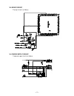
Page 22: ... 20 4 5 DRAWER I F CIRCUIT The drawer open circuit is as follows ...
Page 23: ... 21 4 6 PRINTER CONTROL CIRCUIT The printer control circuit is as follows ...
Page 68: ... 66 8 PCB LAYOUT MAIN PCB E466 1 PCB TOP VIEW ...
Page 69: ... 67 MAIN PCB E466 1 PCB BOTTOM VIEW ...
Page 93: ... 91 TE 2400 KEYBOARD BLOCK 16 15 17 18 19 20 21 22 23 ...
Page 98: ... 96 11 DRAWER DL 2429 for USA 16 17 18 11 8 6 15 14 19 9 10 1 12 20 21 5 4 2 3 5 13 7 ...
Page 104: ... 102 14 DRAWER DL 2799 for UK Canada 12 17 11 8 7 6 9 10 1 18 19 5 4 2 5 16 13 15 14 3 ...


