background image

21

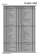
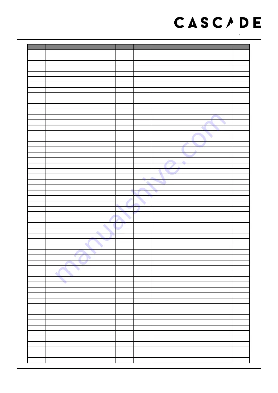
Parts List

P/N

DESCRIPTION

Q'TY

P/N

DESCRIPTION

Q'TY

A

Main Frame

1

A58

Linkage Rod 

1

A1

Ribbed Belt Wheel -  OD360mm

1

A59

Spring

1

A2

Ribbed Belt - 690 J6

1

A60

Stop Ball - OD10mm

1

A3

Magnetic ( OD15 X 7mm )

1

A61

Spacer Block

1

A4

Hex Socket Head Cap Bolt ( M8 X 35mm )

1

A62

Spring

1

A5

Steel - Fan Assembly

1

A63

Bushing ( Ø8 X 12 X 7mm )

1

A6

Plastic Strip

1

A64

Nylon Locknut -  M6

1

A7

Shaped Crank Plate- L

1

A65

Hex Socket Head Cap Bolt ( M6 X 35mm )

1

A8

Shaped Crank Plate- R

1

A66

Steel - Fan Wheel Cover - L

1

A9

Hex Socket Head Cap Bolt  ( M5 X 6mm )

4

A67

Steel - Fan Wheel Cover - R

1

A10

Flat Washer ( M5 X Ø13 X 1T )

4

A68

Front Fan Wheel Cover - L

1

A11

Hex Socket Head Cap Bolt ( M5 X 15mm )

4

A69

Front Fan Wheel Cover - R

1

A12

Hex Nut - M12

4

A70

Chain Cover ( L )

1

A13

Fan Wheel Axle Adjusting Screw - M8

2

A71

Chain Cover ( R )

1

A14

Spacer

2

A72

Sensor Housing

1

A15

Nylon Locknut - M8

2

A73

Phillip Head Self Tapping Screw ( M4 x 12mm )

4

A16

C Clip  - S52

4

A74

Phillip Head Self Tapping Screw ( M4 x 15mm )

4

A17

Linkage Bar

2

A75

Hex Socket Head Cap Bolt ( M6 X 20mm )

1

A18

Bearing - 2205ZZ

2

A76

Plastic Strip Holder

2

A19

Bearing - 6301ZZ

1

A77

Phillip Head Machine Screw ( M4 X 10mm )

2

A20

Metal Spacer -  Ø19 X Ø12.5 X Ø18.7mm

1

A78

Spring

1

A21

Holder Bracket

2

A79

Gasket

1

A22

Fan Wheel Pulley ( OD45 X 80mm )

1

A80

Metal Plate

2

A23

Hex Socket Head Cap Bolt ( M6 X 12mm )

6

B

Front Stabilizer

1

A24

Spring Washer - M8

6

B1

Front Stabilizer End Cap

2

A25

Bearing - 6001

3

B2

Moving Wheel

2

A26

Spacer Ring

1

B3

Allen Head Bolt ( M8 X 40mm )

2

A27

Fan Wheel Axle ( OD12 X 155mm )

1

B4

M8 Capnut

2

A28

Seat Post Mounting Cap

1

B5

Foot Stop

2

A29

Seat Post Reducer Spacer

1

B6

Phillip Head Machine Screw ( M4 x 12mm )

4

A30

Allen Head Bolt ( M6 X 10mm )

2

C

Rear Stabilizer

1

A31

Metal Sleeve - ( Ø10 X 43.2mm )

1

C1

Rear Stabilizer End Cap -  Ø101.6

2

A32

Cam Handle

1

C2

Height Adjustable Lock

2

A33

Speed  Wire

1

C3

Height Adjustable Foot Stop - Ø50

2

A34

Spacer 

2

D1

Dual Action Handle Bar - Mulit Grip ( L )

1

A35

Crank Arm Cover ( R + L ) - Large

2

D2

Dual Action Handle Bar - Mulit Grip ( R )

1

A36

Crank Arm Cover ( R + L ) - Small

2

D5

Bearing - 6003ZZ

4

A37

Crank Axle - M25 X P1.5

1

D6

Phillip Head Machine Screw ( M5 X 8mm )

4

A38

Crank Arm Assembly ( R )

1

D7

Handle Bar End Cap - Low

2

A39

Crank Arm Assembly ( L )

1

D8

Bearing - 6203ZZ

2

A40

Spacer ( Ø25 X 31 X T2mm )

2

E

Console Support Frame

1

A41

Hex Socket Head Cap Bolt ( M8 X 40mm )

4

E1

Console Support Frame End Cap

1

A42

Bearing - 6005ZZ

2

E2

Middle Wire Grommet

2

A43

Axle Adapter Washer

1

E3

Middle Wire

1

A44

Hex Socket Head Cap Bolt ( M6 X 20mm )

1

E4

Hex Socket Flat Head Bolt ( M8 X 25mm )

2

A45

Metal Stop

2

F

Console Assembly

1

A46

Saddle ( LS-A22 )

1

F1

Phillip Head Machine Screw ( M5 X 12mm ) 

4

A47

Saddle Base

1

G

Foot Peg

2

A48

Nylon Locknut - M8

3

H1

Pedal Set - L (Wiwh Mountable Toe Clip & Strap)

1

A49

Spring Washer - M8

3

H2

Pedal Set - R (Wiwh Mountable Toe Clip & Strap)

1

A50

Seat Post

1

I

Plate

2

A51

Hex Socket Head Cap Bolt ( M6 X 16mm )

1

J2

Hex Socket Flat Head Bolt ( M8 X 30mm )

2

A52

Phillip Head Self Tapping Screw ( M6 x 20mm )

6

J3

M8 Nylon Locknut

2

A53

Sliding Post

1

J4

Disc Spring Spacer

2

A54

Square End Cap

1

J5

Hex Socket Flat Head Machine Screw ( M6 X 15mm )

6

A55

Adjustment Grip

1

J6

Allen Head Bolt ( M10 X 20mm )

8

A56

Quick - Released Pivot Axis

1

J7

Hex Socket Head Cap Bolt ( M6 X 8mm )

2

A57

Phillip Head Self Tapping Screw ( M6 X 15mm )

2

cascadehealthandfitness.com

H E A L T H   &   F I T N E S S

R

Summary of Contents for AIR UNLIMITED 402007

Page 1: ...ime target distance target calories INTERVAL 20 10 20 30 CUSTOM TOTAL TIME REST TARGET TIME DISTANCE CALORIES TARGET HR 65 OF 80 OF MAX HR BPM NOHRSIGNAL TARGETHRACHIEVED SPEED UP SLOW DOWN GO TIME DI...

Page 2: ...computer instructions 13 quick start button functions console display and feedback using workout programs how to take care of your Air Unlimited 18 troubleshooting 18 exercising with your Air Unlimit...

Page 3: ...exercising Ensure you warm up well before using the equipment as this will help to prevent muscle strain After eating allow 1 2 hours before exercising as this will help to prevent muscle strain Neve...

Page 4: ...ularly examined for damage and wear This includes any ropes pulleys nuts bolts moving parts bushes chains wheels bearings connection points etc Ensure that you inspect the product regularly at least o...

Page 5: ...x 2 Pedal set x 1pair Front stabilizer x 1 Part No C Rear stabilizer x 1 Disc Spring Spacer Part No E M8 Nylon Locknut Part No E4 Part No I Main Frame Part No A Part No D1 Left Handlebar x 1 Part No D...

Page 6: ...INGS PARTS x 2 Part No J6 Be sure to fit the parts in the same order as the diagrams shown Make sure the bolts are fully tightened with the allen key Make sure the moving wheels on the front stabilize...

Page 7: ...osen the two M10 x 20mm Allen Head Bolt J6 from the cardboard tube and remove the cardboard tube The cardboard tube is used for packaging protection purposes which won t be used again during the assem...

Page 8: ...it on and tighten it with the wrench as shown Attach the End Cap J1 onto the Foot Peg G securely 3 2 Install the Fix Plate Linkage Bar Connect the left Dual Action Handlebar D1 and Linkage Bar with Fi...

Page 9: ...h as shown Attach the End Cap J1 onto the Foot Peg G securely 3 4 Install the Fix Plate Linkage Bar Connect the right Dual Action Handlebar D2 and Linkage Bar with Fix Plate I Disc Spacer J4 M8x30mm S...

Page 10: ...S 5mm Be sure to fit the parts in the same order as the diagrams shown Make sure the screw is fully tightened with the allen key 4 2 Attach the Right Pedal Loosen the Phillip Head Screw J7 fitted on t...

Page 11: ...crews are fully tightened with the screwdriver Make sure the cables are fully connected 5 Attach the Console Support Be sure to fit the parts in the same order as the diagrams shown Take care not to t...

Page 12: ...ust the reach of the Saddle Release the 2 Adjustment Grip A55 after the proper saddle position had found Levelling your Air Unlimited 1 To help you level the Air Unlimited on uneven surface 2 height a...

Page 13: ...h or pause a workout Press and hold to reset the computer start To begin a workout or restart a paused program To decrease values Press and hold for rapid value change enter To confirm the settings To...

Page 14: ...rom zero to 9999 Indicates the current Revolutions Per Minute you are pedalling at Indicates the target to exercise at 65 of your maximum heart rate Indicates the target to exercise at 80 of your maxi...

Page 15: ...at any time The workout summary will displayed on the screen Interval 20 30 Program 1 Make sure the console is switched on 2 Press the interval 20 30 to select the program mode you want 3 The default...

Page 16: ...buttons to set your workout time 1 00 1 59 00 minutes 4 Press enter to confirm your setting 5 Press start to begin the workout and then start pedalling The program will not start until you begin peda...

Page 17: ...tched on 2 Press the target HR to select the program mode you want 3 The default value of 30 is flashing in the AGE window 4 Use the buttons to input your age 10 99 5 Press enter to confirm your setti...

Page 18: ...the equipment in a dry place with as little temperature variation as possible Try to protect from dust and always unplug when not in use if applicable Cleaning Use a warm damp cloth to wipe the surfa...

Page 19: ...should last about 30 minutes and can be done on most days of the week Weight loss To see a significant reduction in body fat your sessions must be a little more intense between 60 and 70 of your estim...

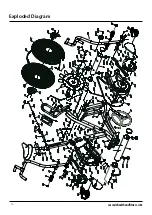
Page 20: ...Exploded Diagram 20 cascadehealthandfitness com...

Page 21: ...Foot Stop 2 A29 Seat Post Reducer Spacer 1 B6 Phillip Head Machine Screw M4 x 12mm 4 A30 Allen Head Bolt M6 X 10mm 2 C Rear Stabilizer 1 A31 Metal Sleeve 10 X 43 2mm 1 C1 Rear Stabilizer End Cap 101...

Page 22: ...22 Cascade Health and Fitness Warranty cascadehealthandfitness com...

Page 23: ......

Page 24: ...H E A L T H F I T N E S S R...

Reviews: