background image

42 


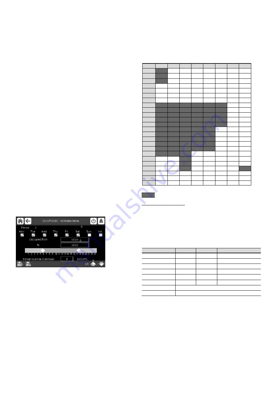
The first timer program (schedule 1, OCCPC01S) 

provides a 

means to automatically switch the unit from an occupied mode to 
an unoccupied mode. The unit is started during occupied periods. 

The second timer program (schedule 2, OCCPC02S) 

provides 

a  means  to  automatically  switch  the  active  setpoint  from  an 
occupied setpoint to an unoccupied setpoint. Cooling setpoint 1 
is  used  during  occupied  periods  and  cooling  setpoint  2  during 
unoccupied periods. 

Occupancy periods 

The control offers the user the possibility of setting eight occupancy 
periods  where  each  occupancy  period  includes  the  following 
elements to be defined: 

■ 

Day of the week: 

Select the days when the period is occupied. 

■ 

Occupancy  time 

(“occupied  from”  to  “occupied  to”): 

Set occupancy hours for the selected days. 

■ 

Timed Override Extension: 

Extend the schedule if necessary. 

This parameter can be used in the case of some unplanned 
events.  Example:  If  the  unit  is  normally  scheduled  to  run 
between 8:00 to 18:00, but one day you want the air-conditioning 
system to operate longer, then set this timed override extension. 
If you set the parameter to 

“2”, then the occupancy will end at 

20:00. 

To set the unit start/stop schedule 

1.  Go to the Main menu. 

2.  Navigate to the Configuration menu (logged-in users only) and 

select 

Schedule Menu 

(SCHEDULE). 

3.  Go to 

OCCPC01S

4.  Select appropriate check boxes to set the unit occupancy on 

specific days. 

5.  Define the time of occupancy. 

6.  When the time schedule is set, the selected period will be 

presented in the form of the green band on the timeline. 

7. 

Press the 

Save 

button to save your changes or the 

Cancel 

button to exit the screen without making modifications. 


Legend: 

1. Selection of days for the time schedule 
2. Start/end of the schedule 
3. Previous time period 
4. Next time period 

Each  program  is  in  unoccupied  mode  unless  a  schedule  time 
period is active. 

If two periods overlap and are both active on the same day, then 
the occupied mode takes priority over the unoccupied period. 


Example: Schedule setting (schedule 1) 


Hour  MON  TUE  WED 

THU 

FRI 

SAT 

SUN 

HOL 

0:00 

P1


1:00 

P1


2:00 

P1


3:00 


4:00 


5:00 


6:00 


7:00 

P2


P2


P3


P4


P4


P5


8:00 

P2


P2


P3


P4


P4


P5


9:00 

P2


P2


P3


P4


P4


P5


10:00 

P2


P2


P3


P4


P4


P5


11:00 

P2


P2


P3


P4


P4


P5


12:00 

P2


P2


P3


P4


P4


13:00 

P2


P2


P3


P4


P4


14:00 

P2


P2


P3


P4


P4


15:00 

P2


P2


P3


P4


P4


16:00 

P2


P2


P3


P4


P4


17:00 

P2


P2


P3


18:00 


P3


19:00 


P3


20:00 


P3


P6


21:00 


22:00 


23:00 


Occupied 

Unoccupied 

MON: 

Monday 

TUE: 

Tuesday 

WED: 

Wednesday 

THU: 

Thursday 

FRI: 

Friday 

SAT: 

Saturday 

SUN: 

Sunday 

HOL: 

Holiday 


Period/Schedule 

Starts at 

Stops at 

Active on (days) 

P1: Period 1 

0:00 

3:00 

Monday 

P2: Period 2 

7:00 

18:00 

 Tuesday 

P3: Period 3 

7:00 

21:00 

Wednesday 

P4: Period 4 

7:00 

17:00 

Th Friday 

P5: Period 5 

7:00 

12:00 

Saturday 

P6: Period 6 

20:00 

21:00 

Holidays 

P7: Period 7 

Not used in this example 

P8: Period 8 

Not used in this example 

6.36-  Holidays 

The control allows the user to define 16 holiday periods, where 
each period is defined by three parameters: the month, the start 
day and the duration of the holiday period. 

During the holiday periods, the controller will be in occupied or 
unoccupied mode, depending on the periods validated as holidays. 
Each  holiday  period  can  be  modified  by  the  user  via  the 
Configuration menu (see also section 5.2). 


Summary of Contents for SmartVu control

Page 1: ...CONTROLS MANUAL SmartVu Control 50 48 UC V UP V 025 220 Original document...

Page 2: ...9 Alarms menu 34 6 STANDARD CONTROL OPERATIONS AND OPTIONS 36 6 1 External thermostat control 36 6 2 Cooling only unit 37 6 3 Single circuit heat pump unit 37 6 4 Dual circuit dual compressor heat pu...

Page 3: ...aying current alarms 49 8 3 E mail notifications 49 8 4 Resetting alarms 49 8 5 Alarm history 49 8 6 Alarm codes 50 9 MAINTENANCE 57 The cover photos are solely for illustration and forms no part of a...

Page 4: ...The information provided herein is solely for the purpose of allowing customers to operate and service Carrier manufactured equipment and it is not to be reproduced modified or used for any other purp...

Page 5: ...ools to move heavy objects Move units carefully and set them down gently CAUTION Only qualified service technicians should be allowed to install and service the equipment 1 2 Safety precautions Only p...

Page 6: ...users tocontrol the unit viathe SmartVuuser interface Provides web connectivity technology Includes the trending functionality Supports Carrier Connect Services Remote connectivity alarm notification...

Page 7: ...7 Fire damper output Defrost mechanism reversible HP Refrigerant leak detection Diagnostics...

Page 8: ...ction 5 6 One Ethernet ports allow for TCP IP communication connection Connections on the bottom side of the controller 3 4 Power supply to boards All boards are supplied from a common 24 VAC supply r...

Page 9: ...lpy contact SIOB2 circuit B DI 04 J1 Supply fan status contact SIOB1 circuit A DI 07 J1 Indoor air flow verification input Fire contact SIOB1 circuit A DI 05 Fire safety input Alarm relay output SIOB1...

Page 10: ...gle circuit unit Y1 compressor 1 on off Y2 compressor 2 on off W additional heating stage 1 on off W2 additional heating stage 2 on off O cycle reversing valve on off heat pump units TSTAT Types TSTAT...

Page 11: ...to be reduced by as much as 3K and to be increased by as much as 3K a button to extend the occupied period extension value entered in the configuration menu see GENCONF menu Supply air temperature sen...

Page 12: ...eft is return fan and the values below are return airflow and RAT Outdoor Air Temperature OAT This parameter is displayed only in case of units fitted with OAT sensor Current freshair supply fan RTU I...

Page 13: ...rol mode Unit is currently stopped blue icon Unit is currently running green icon Alarm menu Press the button to go to the Alarms menu The grey bell means there is currently no alarm active on the uni...

Page 14: ...left 4 8 Screen calibration Thepurposeofscreencalibrationistomakesurethatthesoftware acts correctly upon pressing icons on the user interface To calibrate the screen 1 Press and hold anywhere on the s...

Page 15: ...Configuration menu See section 5 2 Home Previous screen Main Menu System Menu User Login Start Stop Alarms Menu General Parameters Parameters Temperatures Pressures Inputs Outputs Run Times Modes Qui...

Page 16: ...yp 0 to 3 0 Local 0 CCN 1 Remote 2 0 3 blank TSTAT 3 STATUS CHARS8 0 Run Status ALM CHARS8 0 Alarm state min_left 0 to 0 0 min Minutes Left for Start 0 0 HEATCOOL CHARS8 0 Heat Cool status HC_SEL 0 to...

Page 17: ...aving Water Temp 0 0 SCT_A 0 to 0 0 F Saturated Condensing T A 0 0 SST_A 0 to 0 0 F Saturated Suction Temp A 0 0 SUCT_A 0 to 0 0 F EXV Suction Temp A 0 0 DEFRT_A 0 to 0 0 F Defrost Temperature A 0 0 S...

Page 18: ...tch 0 1 SP_SW1 OPEN_CLOSE 0 Remote Setpoint Switch 1 0 1 SP_SW2 OPEN_CLOSE 0 Remote Setpoint Switch 2 0 1 lim_sw1 OPEN_CLOSE 0 Limit Switch 0 1 HS_FBK OPEN_CLOSE 0 Heat Stages status 0 1 PRE_HS OPEN_C...

Page 19: ...E hpsw_b OPEN_CLOSE 0 High Pressure Switch B 0 1 hpsw_c OPEN_CLOSE 0 High Pressure Switch THR 0 1 exvA_fbk 0 to 0 0 EXV Position Circuit A 0 0 exvB_fbk 0 to 0 0 EXV Position Circuit B 0 0 exvC_fbk 0 t...

Page 20: ...Output 0 1 cp_c2 OFF_ON 0 THR Compressor 2 Output 0 1 rv_c OFF_ON 0 4Way Refrig Valve THR 0 1 ecopos 0 to 0 0 Economizer Position 0 0 gas_on OFF_ON 0 Modulated Gas Enable 0 1 gas_v 0 to 0 0 Modulated...

Page 21: ...0 0 EXV Position Circuit THR 0 0 hs_1 OFF_ON 0 Heater Stage 1 0 1 hs_2 OFF_ON 0 Heater Stage 2 0 1 hs_3 OFF_ON 0 Heater Stage 3 0 1 hs_4 OFF_ON 0 Heater Stage 4 0 1 pre_hs_1 OFF_ON 0 Pre heater Stage...

Page 22: ...s Compressor A2 Hours 0 0 st_cp_a2 0 to 0 0 Compressor A2 Starts 0 0 hr_cp_b1 0 to 0 0 hours Compressor B1 Hours 0 0 st_cp_b1 0 to 0 0 Compressor B1 Starts 0 0 hr_cp_b2 0 to 0 0 hours Compressor B2 Ho...

Page 23: ...1 m_dehumi NO_YES 0 Dehumidification Mode 0 1 m_iaq NO_YES 0 IAQ Mode 0 1 m_gas NO_YES 0 OAT Gas Threshold 0 1 m_fire NO_YES 0 Fire Shutdown Active 0 1 m_enth NO_YES 0 Enthalpy Lockout 0 1 m_start NO...

Page 24: ...T High Limit 60 110 purg_du 1 to 5 2 min Purge Duration 1 5 iaq_sp 50 to 10000 700 IAQ Setpoint 50 10000 Trendings TRENDING Name Status Unit Displayed text Description GENUNIT_cap_t 0 to 100 Perecent...

Page 25: ...n menu Date Time Configuration Home Previous screen Main Menu User Login Start Stop Alarms Menu Genunit Config User Configuration Hea Cool Config Schedule Menu Holiday Menu Reset Config Configuration...

Page 26: ...NO_YES 0 Thermostat Control 0 1 frst_sel NO_YES 0 Frost Protection Select 0 1 spt_ctrl 0 to 4 0 SPT Calculation Select 0 4 blank 0 Average Temp Meth blank 1 High Temp Sensor blank 2 Low Temp Sensor bl...

Page 27: ...ARTVU CONTROL MENU STRUCTURE synoptic NO_YES 0 Synoptic Is Displayed 0 1 User Configuration USERCONF Point Name Status Default Unit Description Low Limit High Limit use_pass 1 to 9999 11 User Password...

Page 28: ...mer months and back again in the fall in order to make better use of natural daylight Greenwich Mean Time UTC Location Time zone YYYY MM DD HH MM SS Date Time Current date and time must be set manuall...

Page 29: ...ule setting please see section 6 24 5 4 Holiday menu The Holiday menu allows the user to set up to 16 holiday periods which are defined by the start month start day and duration Holiday Menu HOLIDAY I...

Page 30: ...ion RAM usage 0 to 100 FLASH Memory utilization Flash memory usage Depends on the selected language English by default EOL Resistor Menu EOLRES Status Default Displayed text Description disable enable...

Page 31: ...me zone YYYY MM DD HH MM SS Date Time Current date and time must be set manually no yes Today is a Holiday Information about holidays read only Please note that holidays are set in the Holiday menu se...

Page 32: ...NN N SDK Version SDK version number NN UI Version User interface version CARRIER Brand Brand name Depends on the selected language English by default Hardware Info Menu HWINFO Status Displayed text De...

Page 33: ...ess the User Login button and then select User Login 2 Press the Password box 3 Provide the password 11 and press the Confirm button 4 The User Login screen appears 5 6 3 User password User password c...

Page 34: ...layed 5 7 3 Unit stop To stop the unit 1 Press the Start Stop button 2 ConfirmtheunitshutdownbypressingConfirmStoporcancel the unit shutdown by pressing the Backbutton Unit start stop screen operating...

Page 35: ......

Page 36: ...ocess failure compressor failure and VFD drives IMPORTANT For more information about alarms please go to section 8 6 Current Alarms Menu CUR_ALM No Name Date Hour Alarm text 1 Alarm YYYY MM DD HH MM A...

Page 37: ...urrent Alarm 1 Alarm code see section 8 6 4 alarm_2c Current Alarm 2 Alarm code see section 8 6 5 alarm_3c Current Alarm 3 Alarm code see section 8 6 6 alarm_4c Current Alarm 4 Alarm code see section...

Page 38: ...ed 6 3 Single circuit heat pump unit Contact G open The internal fan is stopped and the economizer is closed Contact G closed The internal fan is activated and the economizer is opened to its minimum...

Page 39: ...le 1 Remote start stop contact status Onoff_sw Start stop contact status can be used to control the unit state in the Remote operating type G This contact is used when unit is in thermostat operating...

Page 40: ...In this case the function is generally used to limit the difference between the indoor and outdoor temperatures in order to prevent thermal shock IMPORTANT It is not possible to use both types of off...

Page 41: ...be vspd_max 10 Volts 6 16 Head pressure control Condensing pressure control is automatically ensured by a two speed fan no adjustment 6 17 Defrost function Defrost is activated when the unit is in hea...

Page 42: ...horised If the unit is fitted with a power exhaust fan this shall be open if the position of the economizer is in excess of 50 this threshold may be modified by Carrier Service 6 22 Purge This functio...

Page 43: ...is in same status with the supply fan and the return fan s speed is command However any faults active when the supply is interrupted are saved and may in certain cases prevent a circuit or a unit from...

Page 44: ...Press the Save button to save your changes or the Cancel button to exit the screen without making modifications Legend 1 Selection of days for the time schedule 2 Start end of the schedule 3 Previous...

Page 45: ...on to display the graph showing trends for the set of selected parameters Set the time range start end dates and time and press the Arrowbutton todisplaythegraphshowingtheperformance of the unit withi...

Page 46: ...y the unit IP address Example https 169 254 1 1 3 Press Enter 4 The web interface will be loaded IMPORTANT Three users can be connected simultaneously with no priority between them The last modificati...

Page 47: ...sting alarms have been reset To define e mail recipients 1 Press theMain menu buttonandnavigatetotheConfiguration menu 2 Go to the Network menu 2 Select Email Configuration EMAILCFG 3 Define user e ma...

Page 48: ...r installation fault Circuit is shut down 15 Pr 02 Circuit B Discharge Transducer As above As above As above 16 Pr 03 Circuit THR Discharge Transducer As above As above As above 17 Pr 04 Circuit A Suc...

Page 49: ...d low suction temp overrides Manual Pressure sensor defective or refrigerant charge too low Circuit is shut down 41 P 41 Circuit B Repeated low suction temp overrides Manual As above As above 42 P 42...

Page 50: ...Superheat B Manual Circuit B shuts down 66 P 10 High Suction Superheat THR As above As above Circuit THR shuts down 67 P 11 Low Suction Superheat A Manual Circuit A shuts down 68 P 12 Low Suction Sup...

Page 51: ...ensure your Carrier equipment is regularly inspected by Carrier Service specialists so that any malfunction is detected and corrected quickly and no serious damage can occur to your equipment The Car...

Page 52: ...o 10508 04 2019 Supersedes order No 10508 04 2019 Manufactured by Carrier SCS Montluel France Manufacturer reserves the right to change any product specifications without notice Printed in the Europea...

Reviews: