


41
condenser flow switch, temperature sensors and refrigeration
devices to allow up to 100% of the condenser heat to be re-
claimed for hot water. This means that this water-cooled con-
denser, which is in parallel with the standard air-cooled con-
denser, is capable of capturing all of the heat available from the
chiller condensing process. The leaving water temperature can
reach at maximum 131 F (55 C) under steady state and con-
stant hot water flow conditions with an allowable hot water
temperature range of 68 to 131 F (20 to 55 C). The heat reclaim
condenser fluid connections are at the end of the unit opposite
the control panel. The temperature sensor and the condenser
flow switch are mounted in the nozzles and are wired in the
control box. Refer to the Controls and Troubleshooting Book
for detailed operational information.
The heat reclaim condenser has water-side Victaulic-type
connections (follow connection directions as provided by the
coupling manufacturer). Provide proper support for the piping.
If compressor and cooler grilles have been added, holes must
be cut for field piping and insulation. A field-supplied strainer
with a minimum size of 20 mesh must be installed within 10 ft
(3.0 m) of the inlet to the heat reclaim condenser. See Fig. 32
for a typical piping diagram of the heat reclaim condenser and
3-way valve location. All piping must follow standard piping
techniques. Refer to Carrier System Design Manual or appro-
priate ASHRAE (American Society of Heating, Refrigerating,
and Air-Conditioning Engineers) handbook for details.
Two drain connections are provided, one in each head of the
condenser.
HEAD PRESSURE CONTROL — A form of head pressure
control is required while in the heat reclaim mode. In order to
meet this requirement, a properly sized 3-way valve must be
field-installed. This valve will facilitate cold water start-up
(water temperatures below 68 F [20 C]), and it also will be able
to maintain proper head pressure during heat reclaim operation.
Since the hot water temperature at start-up may be very low,
the 3-way valve is to be located as close to the heating con-
denser as possible so that this valve can quickly accomplish its
purpose of maintaining the minimum required head pressure.
Locate the 3-way valve within 40 ft (12.2 m) of the heating
condenser if the circulating pump is located between the 3-way
valve and the heat reclaim condenser. See Fig. 33A. If the
pumps are too far away from the condenser, a second option is
to install the 3-way control valve close to the condenser. See
Fig. 33B. The 30RB unit uses an anolog output to control this
valve.
CAUTION
Do not circulate water through unit without strainers in
place. Failure to use the strainers represents abuse and may
impair or otherwise negatively affect the Carrier product
warranty.
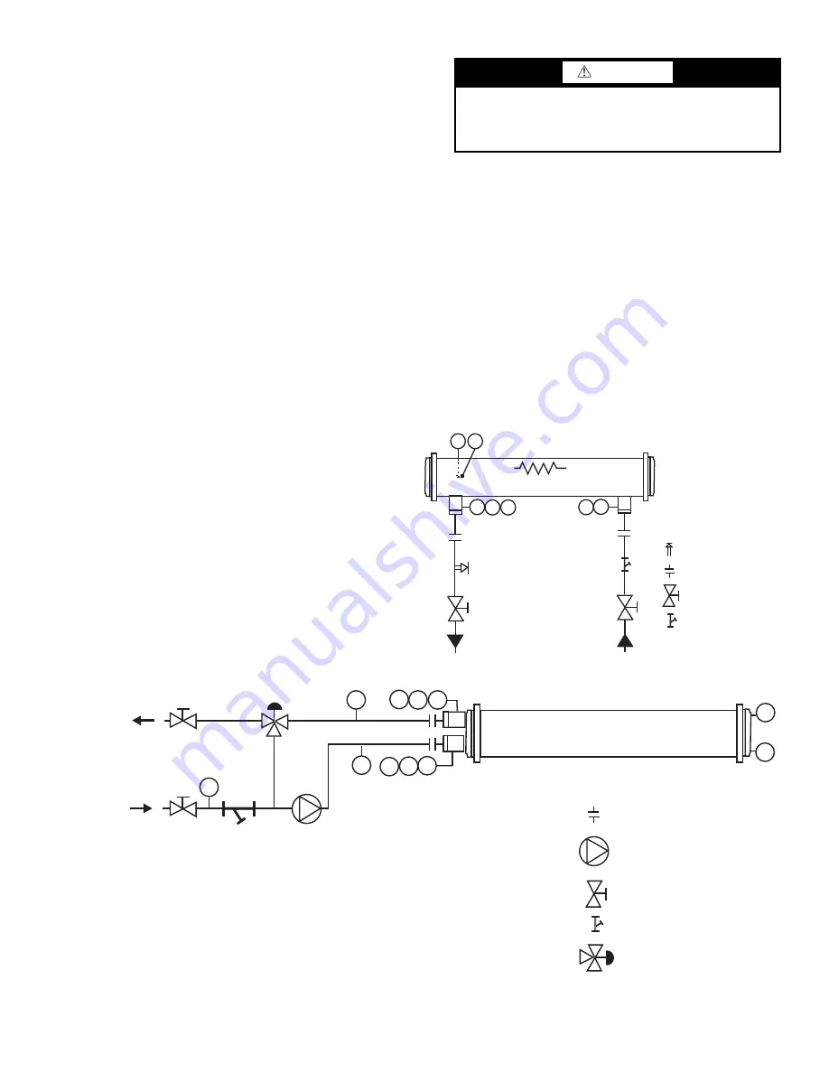
T1
T2
FS PP
PP
D
V
Heater (Optional)
Chilled Water
Out
Chilled Water
In
Isolation Valve*
20 Mesh Strainer†
Flexible Connections*
Pressure Relief*
LEGEND
*Field-supplied and installed.
D
—
Drain,
3
/
4
-in. NPT
FS
—
Flow Switch
PP
—
Pipe Plug,
1
/
4
-in. NPT
T1
—
Leaving Water Thermistor
T2
—
Entering Water Thermistor
V
—
Vent,
1
/
4
-in. NPT
Fig. 31 — Typical Piping Diagram on 30RB Units without Hydronic Package
T1
T2
FS PP
PP
HEAT RECLAIM CONDENSER
HEAT
RECLAIM
RETURN
HEAT
RECLAIM
SUPPLY
Pump*
Isolation Valve*
Flexible Connections*
20 Mesh Strainer*, installed
within 10 ft (3 m) of condenser
inlet
Three-Way Valve*
V*
D*
R
D
V
D
a30-5321
Fig. 32 — Typical Piping Diagram on 30RB Units with Heat Reclaim Option
LEGEND
*Field-supplied and installed.
D*
—
Drain, Field Supplied
D
—
Drain,
3
/
8
-in. NPT
FS
—
Flow Switch
PP —
Pipe Plug,
1
/
4
-in. NPT
R
—
Pressure Relief
T1
—
Leaving Water Thermistor
T2
—
Entering Water Thermistor
V*
—
Vent, Field Supplied
V
—
Vent,
3
/
8
-in. NPT
Summary of Contents for MINIMUM LOAD CONTROL ACCESSORY 30RB060-390
Page 36: ...36 Fig 24 Unit Rigging Label Detail 30RB060 150...
Page 37: ...37 Fig 25 Unit Rigging Label Detail 30RB160 300...
Page 74: ......
Page 75: ......