background image

NOTE:

If the variable-speed indoor equipment (furnace or fan

coil) cannot be found, the User Interface will display

CANNOT

COMMUNICATE WITH INDOOR UNIT

. This MUST be

corrected before the initial power up sequence can continue. If
indoor unit is found, but outdoor unit is not found,

OUTDOOR

UNIT NOT IDENTIFIED

will appear. Proceed to the next section

for Outdoor Unit Identification.

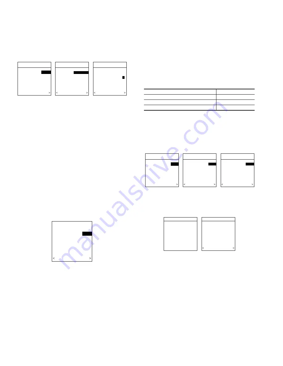
SECTION 2 — SELECTING OUTDOOR UNIT

If there is no communicating outdoor unit, the screen, shown in
Fig. 16, will appear. Press either Time or Temp +/- buttons to
select AC (air conditioner), HP (heat pump), or None (no unit
installed). Press right-side button to continue to next screen.

If either AC or HP has been selected as the outdoor unit type, the
middle screen will appear (See Fig. 16). Press either Time or Temp
+/- buttons to select appropriate Btu size of outdoor unit, then press
right side button to continue. If a NIM (Network Interface Module)
is applied for non-communicating two-speed outdoor equipment,
select 1 or 2-speed compressor operation , and press right-side
button to continue.

NOTE:

Range of outdoor unit Btu selection is limited by model

number of indoor unit installed. The Infinity Zone Control™ will
not allow an outdoor unit size that is not supported by the installed
indoor unit.

NOTE:

On new system installations, the model and serial number

will be recognized and displayed. On any indoor/outdoor board
replacements, the equipment will be recognized but the exact
model/serial number will not be displayed.

SECTION 3 — SELECTING ELECTRIC HEATER

If indoor unit is a fan coil and the electric heater is not
self-identifying,

ELECTRIC HEATER NOT IDENTIFIED

will

appear (See Fig. 17). Press either Time or Temp +/- buttons to
select appropriate size of electric heater installed, then press
right-side button to continue.

NOTE:

Range of electric heaters available is limited by model

number of the fan coil installed. The Infinity Zone Control™ will
not allow an electric heater size that is not supported by the
installed fan coil.

SECTION 4 — SELECTING ACCESSORIES

Once the indoor and outdoor equipment have been found or
entered, the following screens will appear allowing the Installer to
select the AIR FILTER TYPE; HUMIDIFIER INSTALLED; and
UV LIGHTS INSTALLED

(See Fig. 18). Use either Time or

Temp +/- buttons to make appropriate selections in the highlighted
area on the display screen. Press right-side button to continue (or
advance) to the next screen.

AIR FILTER TYPE— This accessory screen will appear first.
The installer will need to enter the type of filter (MEDIA, EAC, or
both). See Table 1 and make a selection using Time or Temp +/-
button, then press right-side button to continue.

HUMIDIFIER INSTALLED — This will appear after the Air
Filter Type screen. Select whether a humidifier is installed on the
system, YES or NO, then press right-side button to continue.

UV LIGHTS INSTALLED— This screen will appear to select
whether UV lights are installed on the system, select YES or NO,
then press right-side button to continue.

SECTION 5 — ZONING

SEARCHING FOR ZONE EQUIPMENT will appear on the
screen to identify the number of zones detected. This screen will
show Zone 1, Zone 2, etc. and indicate all zones having either a
remote room sensor, or smart sensors associated with them. If the
system contains smart sensors, they must be assigned a zone
number before continuing. See Smart Sensor Installation Instruc-
tions on how to assign Smart Sensors to their respective zones.
When finished, press right-side button to continue. See Fig. 18a.

Fig. 16—Selecting Outdoor Unit

A03196

OUTDOOR UNIT

NOT IDENTIFIED

 SELECT TYPE:       

NONE

 NONE, AC, HP

PRESS +/- TO MAKE

SELECTION

           CONTINUE

OUTDOOR UNIT

ENTER HEAT PUMP
SIZE


36000 BTU

18000 TO 60000 BTU

PRESS +/- TO MAKE

SELECTION

   BACK          CONTINUE

OUTDOOR UNIT

HEAT PUMP

ENTER NUMBER OF
SPEEDS, 1 or 2:              

1

PRESS +/- TO MAKE

SELECTION

   BACK          CONTINUE

Fig. 17—Selecting Electric Heater

A03197

ELECTRIC HEATER

NOT IDENTIFIED

 ENTER SIZE:            

5 KW

 NONE, 5,10,15 KW

PRESS +/- TO MAKE

SELECTION

  BACK           CONTINUE

INSTALLED FILTER

MENU SELECTION

1 Inch to 4 inch media

MEDIA

High voltage EAC

EAC

High voltage EAC + 1 to 4 inch media

MEDIA + EAC

Table 1 — Filter Selection

Fig. 18—Accessories — UV Lights

A03198

ACCESSORIES

HUMIDIFIER
INSTALLED?          

    YES

PRESS +/- TO MAKE

SELECTION

   BACK          CONTINUE

ACCESSORIES

U.V. LIGHTS
INSTALLED?          

    YES

PRESS +/- TO MAKE

SELECTION

   BACK          CONTINUE

ACCESSORIES

AIR FILTER TYPE: 
EAC

EAC

MEDIA
MEDIA + EAC

PRESS +/- TO MAKE

SELECTION

                      CONTINUE

AIR FILTER MEDIA TYPE

HUMIDIFIER INSTALLED?

U.V. LIGHTS INSTALLED?

ZONING

SEARCHING FOR

ZONE EQUIPMENT

WORKING

ZONING

ZONE 1

UI

ZONE 2

RS

ZONE 3

RS

ZONE 4

RS

UI=USER INTERFACE
RS=REMOTE SENSOR
SS=SMART SENSOR
   BACK               CONTINUE

Fig. 18a — Zoning

A04084

6

Summary of Contents for Infinity SYSTXCCUIZ01

Page 1: ...or fan coils are variable speed and multi stage for maximum flexibility efficiency and comfort They support controlled ventilation humidification dehumidification and air quality control Either an Infinity dual capacity communicating or a standard 24 vac controlled outdoor unit may be used When using conventional outdoor units the Infinity furnace or fan coil provides the 24 volt signals needed to...

Page 2: ...te Room Sensor has priority over the Smart Sensor WIRING CONSIDERATIONS Ordinary thermostat wire is recommended Use 22 AWG or larger for normal wiring applica tions Continuous wire lengths over 100 ft should use 20 AWG or larger NOTE ABCD bus wiring only requires a four wire connection however it is good practice to run thermostat cable having more than four wires in the event of a damaged or brok...

Page 3: ...re to follow this warning could result in personal injury or death Before installing Infinity Zone Control turn off all power to equipment There may be more than one power source to disconnect 1 Turn off all power to equipment 2 If an existing User Interface or control is being replaced a Remove existing control from wall b Disconnect wires from existing control Fig 2 Infinity Zone Control A03185 ...

Page 4: ...eaks can affect operation 10 Attach Infinity Zone Control to the mounting plastic by lining up the plastic guides on the back of the control with the opening on the mounting plastic and push on 11 Perform installation of all other system equipment i e zone sensors dampers humidifier ventilator UV lights etc 12 Turn on power to equipment EQUIPMENT WIRING DIAGRAMS See wiring diagrams Fig 12 13 and 1...

Page 5: ...to become familiar with key function buttons such as System On Off Zone Fan Left Side and Right Side buttons etc These function buttons will be used frequently during setup SECTION 1 POWER UP SEQUENCE This section addresses initial power up or commissioning of a new Infinity Zone Control The User Interface will communi cate and identify all Infinity components in the system The following is a typi...

Page 6: ...IGHTS INSTALLED See Fig 18 Use either Time or Temp buttons to make appropriate selections in the highlighted area on the display screen Press right side button to continue or advance to the next screen AIR FILTER TYPE This accessory screen will appear first The installer will need to enter the type of filter MEDIA EAC or both See Table 1 and make a selection using Time or Temp button then press ri...

Page 7: ...irmed when the red LED next to the red HEAT button is lit 2 Use the TEMP button to select your desired heating temperature 3 The default time for temporarily overriding the temperature schedule is 2 00 HRS as indicated by the text on the lower left NOTE Override time will not appear if programming has been turned off 4 You can change the temporary override time in 15 minute increments by pressing ...

Page 8: ...t configuration made by dip switches Fig 23 shows all the information that can be found in the SETUP menu Setup THERMOSTAT AUTO MODE SETUP Enable Disable Auto Changeover mode default Enable Auto Changeover Time may be adjusted 5 to 120 minutes default 30 minutes When Auto mode is enabled factory default a change from heat to cool or vice versa will not occur until an opposite mode demand has exist...

Page 9: ...lt LOW HIGH Controls the staging of the furnace SYSTEM setting will allow the Infinity Zone Control to determine furnace staging LOW will only run the low stage of furnace heat HIGH will only run the high stage of furnace heat OFF DELAY 90 seconds 120 seconds default 150 seconds 180 seconds Amount of time the blower will continue to run after heating has shut off LOCKOUT TEMP NONE default 5 to 55 ...

Page 10: ...ault 90 Interval at which the Clean Ventilator Pre filter notification will turn on UV LIGHTS INSTALLED NO YES If YES indicates to the system whether UV lights are installed CHANGE INTERVAL 6 to 48 months operation time default 12 months Interval at which the Change UV Lights notification will be displayed Setup SYSTEM MAINTENANCE REMIND OWNER OF ROUTINE MAINTENANCE EVERY This setup is used to adj...

Page 11: ... room sensor is disconnected the Zone 2 damper will now open as indicated on the User Interface display The word FAIL will also be displayed instead of the actual temperature for Zone 2 Reconnect Zone 2 sensor and try all remaining sensors one at a time in the system Smart Sensors may also be checked see Smart Sensor Installation Instructions for procedure AIRFLOW LIMITS Low Medium High default Ma...

Page 12: ...vered to each zone Damper position range from 0 to 15 0 closed 15 open Service LAST 10 SYSTEM FAULTS This screen will show last 10 faults that occurred throughout the system Each fault has the time and date incident recorded Service technician should enter current date in TODAY S DATE menu section BEFORE checking and logging the last 10 system faults Each fault has a two letter acronym preceding t...

Page 13: ...um On Time In normal operation when a stage turns on it will remain on for a minimum of three minutes If the set point is changed this timer is automatically cancelled allowing the equipment to turn off imme diately when the demand is removed Heat Cool Set points Desired Temperatures A minimum difference of 2 default is enforced between heating and cooling desired temperatures This is done by allo...

Page 14: ...sts between the actual room temperature and operating set point yet the equipment does not turn on 1 The zone airflow limit may be set too low Perform the Zone Airflow Limit Checkout procedure raise airflow limit setting if possible Some zones provide too much airflow and are noisy 1 The zone airflow limit may be set too high Perform the Zone Airflow Limit Checkout procedure lower airflow limit se...

Page 15: ...le NIM communication fault Defrost Error defrost signal on for more than 15 minutes The user can press the right side button to dismiss the notice The regular run mode screen will then appear except SYSTEM MALFUNCTION will appear in place of the day time If the error has not disappeared within 24 hours the above display will return If the error code disappears SYSTEM MALFUNCTION will disappear and...

Page 16: ...231 uiz01 1si Manufacturer reserves the right to discontinue or change at any time specifications or designs without notice and without incurring obligations Book 1 4 Tab misc misc PC 101 Catalog No 809 50025 Printed in U S A Form UIZ01 1SI Pg 16 03 04 Replaces NEW ...

Reviews: