


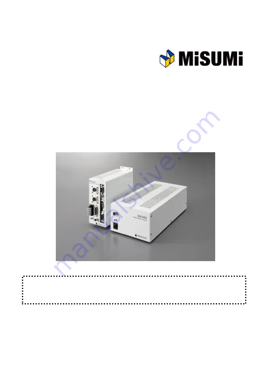
Stepping Motor Controller
MSCTL102 Series/MSCTL112 Series Operation Manual
Ver 1.01 (02.13.2015)
Remarks
MSCTL102/112 Series(MISUMI products) are same as DS102/112 Series that are made by Suruga Seiki.
All of DS102/112 series that are mentioned in the operation manual indicate MSCTL102/112.
MISUMI CO., LTD.
SURUGA SEIKI CO., LTD.
Summary of Contents for DS102MS
Page 166: ...166...


