background image

indoor furnace or fan coil OAT terminals. When OAT sensor is
applied, the Infinity System will provide enhanced system features
and benefits.

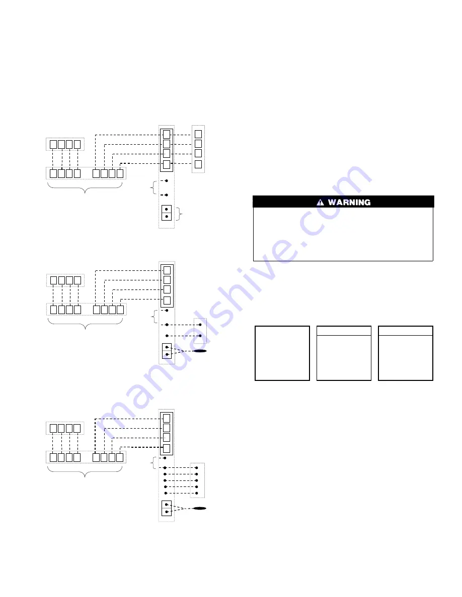
See wiring diagram Fig. 14 for connecting an Infinity FE fan coil
with a 1-speed heat pump (non-communicating outdoor unit).
When OAT is applied, the Infinity system will provide enhanced
system features and benefits.

NOTE:

For other applications not listed, refer to the Network

Interface Module (NIM) Installation Instructions.

HUMIDIFIER CONNECTION — A 24vac bypass or fan
powered humidifier may be installed.

NOTE:

Do Not Use a traditional humidistat to control humidifier

operation. If a humidifier is installed, let the Infinity™ Zone
Control operate humidifier.

Bypass Humidifiers — A bypass humidifier should be wired
directly to the furnace or fan coil HUM and 24vac COM terminals.
The Infinity Zone Control will automatically energize the HUM
output during a call for humidification.

Fan Powered Humidifiers — Most fan powered humidifiers
produce internal 24vac in order to energize upon a switch or
contact closure. For this application, a 24vac N.O. Isolation Relay
(DPST) MUST be used to prevent mixing the internal humidifier
power with the indoor equipment transformer. Applying 24vac
isolation relay coil to furnace or fan coil HUM and COM terminals
will allow the Infinity Zone Control to automatically energize the
HUM output during a call for humidification. The N.O. relay
contacts will be used to energize the humidifier. See fan powered
humidifier installation instructions for more details.

FIRE OR EQUIPMENT HAZARD
Failure to follow this warning could result in equipment
damage or fire.
Do not apply 24vac fan powered humidifier (with internal
power supply) direct to indoor unit HUM and COM termi-
nals.

INITIAL POWER-UP

NOTE:

Refer to Functional Overview (Fig. 11) to become

familiar with key function buttons such as

System On/Off

,

Zone

,

Fan

,

Left-Side

and

Right-Side

buttons, etc. These

function buttons will be used frequently during setup.

SECTION 1 — POWER UP SEQUENCE

This section addresses initial power up (or commissioning) of a
new Infinity Zone Control™. The User Interface will communi-
cate and identify all Infinity components in the system. The
following is a typical example for a communicating Variable-
Speed Furnace / Fan Coil with a 2-spd. Air Conditioner / Heat
Pump (including Dual Fuel).

The User Interface display will light up and indicate that it is now

ESTABLISHING COMMUNICATIONS WITH EQUIPMENT

PLEASE WAIT

. The User Interface will automatically continue

by

SEARCHING FOR INDOOR EQUIPMENT

, followed by

SEARCHING FOR OUTDOOR EQUIPMENT

(See Fig. 15).

Once the indoor and outdoor equipment has been found, the
Installer will be asked to select Accessories. Proceed to Section 4.
Selecting Accessories.

A

B

C

D

Zone Control

User Interface &

Smart Sensor(s)

Green

Yellow

White

Red

OAT

HUM

COM
24V

Humidifier

Connection

A

B

C

D

2-Spd. AC or HP

OAT

Sensor

(Optional)

A

B

C

D

A

B

C

D

Damper

Control

module

A

B

C

D

Indoor

Unit

Fig. 12 — Communicating Indoor Unit w/2-Speed

Puron™ Communicating Outdoor Unit

A04018

A

B

C

D

Zone Control

User Interface &

Smart Sensor(s)

Green

Yellow

White

Red

OAT

HUM

COM
24V

Humidifier

Connection

OAT

Sensor

A B

C

D

A

B C

D

Damper

Control
module

A

B

C

D

Indoor

Unit

C

Y

1-Spd. AC

Y/Y2

Fig. 13 — Connection Diagram for Furnace or FE

Fan Coil with 1-Speed AC

A04019

A

B

C

D

Zone Control

User Interface &

Smart Sensor(s)

Green

Yellow

White

Red

A

B

C

D

A

B

C

D

Damper

Control

module

A

B

C

D

Variable-Speed

Fan Coil

1-Spd. HP

HUM

C

Y

W2

 Y

O

C

R

O

R

W

OAT

OAT

Sensor

Humidifier

Connection

Fig. 14 — Connection Diagram for FE Fan Coil with

1-Speed HP

A04020

Fig. 15 — Power Up Sequence

A03195

   ESTABLISHING
COMMUNICATIONS


    WITH EQUIPMENT 

  PLEASE WAIT

 SOFTWARE

VERSION

INDOOR UNIT

SEARCHING FOR

INDOOR EQUIPMENT

WORKING

OUTDOOR UNIT

SEARCHING FOR

OUTDOOR EQUIPMENT

WORKING

5

Summary of Contents for Infinity SYSTXCCUIZ01

Page 1: ...or fan coils are variable speed and multi stage for maximum flexibility efficiency and comfort They support controlled ventilation humidification dehumidification and air quality control Either an Infinity dual capacity communicating or a standard 24 vac controlled outdoor unit may be used When using conventional outdoor units the Infinity furnace or fan coil provides the 24 volt signals needed to...

Page 2: ...te Room Sensor has priority over the Smart Sensor WIRING CONSIDERATIONS Ordinary thermostat wire is recommended Use 22 AWG or larger for normal wiring applica tions Continuous wire lengths over 100 ft should use 20 AWG or larger NOTE ABCD bus wiring only requires a four wire connection however it is good practice to run thermostat cable having more than four wires in the event of a damaged or brok...

Page 3: ...re to follow this warning could result in personal injury or death Before installing Infinity Zone Control turn off all power to equipment There may be more than one power source to disconnect 1 Turn off all power to equipment 2 If an existing User Interface or control is being replaced a Remove existing control from wall b Disconnect wires from existing control Fig 2 Infinity Zone Control A03185 ...

Page 4: ...eaks can affect operation 10 Attach Infinity Zone Control to the mounting plastic by lining up the plastic guides on the back of the control with the opening on the mounting plastic and push on 11 Perform installation of all other system equipment i e zone sensors dampers humidifier ventilator UV lights etc 12 Turn on power to equipment EQUIPMENT WIRING DIAGRAMS See wiring diagrams Fig 12 13 and 1...

Page 5: ...to become familiar with key function buttons such as System On Off Zone Fan Left Side and Right Side buttons etc These function buttons will be used frequently during setup SECTION 1 POWER UP SEQUENCE This section addresses initial power up or commissioning of a new Infinity Zone Control The User Interface will communi cate and identify all Infinity components in the system The following is a typi...

Page 6: ...IGHTS INSTALLED See Fig 18 Use either Time or Temp buttons to make appropriate selections in the highlighted area on the display screen Press right side button to continue or advance to the next screen AIR FILTER TYPE This accessory screen will appear first The installer will need to enter the type of filter MEDIA EAC or both See Table 1 and make a selection using Time or Temp button then press ri...

Page 7: ...irmed when the red LED next to the red HEAT button is lit 2 Use the TEMP button to select your desired heating temperature 3 The default time for temporarily overriding the temperature schedule is 2 00 HRS as indicated by the text on the lower left NOTE Override time will not appear if programming has been turned off 4 You can change the temporary override time in 15 minute increments by pressing ...

Page 8: ...t configuration made by dip switches Fig 23 shows all the information that can be found in the SETUP menu Setup THERMOSTAT AUTO MODE SETUP Enable Disable Auto Changeover mode default Enable Auto Changeover Time may be adjusted 5 to 120 minutes default 30 minutes When Auto mode is enabled factory default a change from heat to cool or vice versa will not occur until an opposite mode demand has exist...

Page 9: ...lt LOW HIGH Controls the staging of the furnace SYSTEM setting will allow the Infinity Zone Control to determine furnace staging LOW will only run the low stage of furnace heat HIGH will only run the high stage of furnace heat OFF DELAY 90 seconds 120 seconds default 150 seconds 180 seconds Amount of time the blower will continue to run after heating has shut off LOCKOUT TEMP NONE default 5 to 55 ...

Page 10: ...ault 90 Interval at which the Clean Ventilator Pre filter notification will turn on UV LIGHTS INSTALLED NO YES If YES indicates to the system whether UV lights are installed CHANGE INTERVAL 6 to 48 months operation time default 12 months Interval at which the Change UV Lights notification will be displayed Setup SYSTEM MAINTENANCE REMIND OWNER OF ROUTINE MAINTENANCE EVERY This setup is used to adj...

Page 11: ... room sensor is disconnected the Zone 2 damper will now open as indicated on the User Interface display The word FAIL will also be displayed instead of the actual temperature for Zone 2 Reconnect Zone 2 sensor and try all remaining sensors one at a time in the system Smart Sensors may also be checked see Smart Sensor Installation Instructions for procedure AIRFLOW LIMITS Low Medium High default Ma...

Page 12: ...vered to each zone Damper position range from 0 to 15 0 closed 15 open Service LAST 10 SYSTEM FAULTS This screen will show last 10 faults that occurred throughout the system Each fault has the time and date incident recorded Service technician should enter current date in TODAY S DATE menu section BEFORE checking and logging the last 10 system faults Each fault has a two letter acronym preceding t...

Page 13: ...um On Time In normal operation when a stage turns on it will remain on for a minimum of three minutes If the set point is changed this timer is automatically cancelled allowing the equipment to turn off imme diately when the demand is removed Heat Cool Set points Desired Temperatures A minimum difference of 2 default is enforced between heating and cooling desired temperatures This is done by allo...

Page 14: ...sts between the actual room temperature and operating set point yet the equipment does not turn on 1 The zone airflow limit may be set too low Perform the Zone Airflow Limit Checkout procedure raise airflow limit setting if possible Some zones provide too much airflow and are noisy 1 The zone airflow limit may be set too high Perform the Zone Airflow Limit Checkout procedure lower airflow limit se...

Page 15: ...le NIM communication fault Defrost Error defrost signal on for more than 15 minutes The user can press the right side button to dismiss the notice The regular run mode screen will then appear except SYSTEM MALFUNCTION will appear in place of the day time If the error has not disappeared within 24 hours the above display will return If the error code disappears SYSTEM MALFUNCTION will disappear and...

Page 16: ...231 uiz01 1si Manufacturer reserves the right to discontinue or change at any time specifications or designs without notice and without incurring obligations Book 1 4 Tab misc misc PC 101 Catalog No 809 50025 Printed in U S A Form UIZ01 1SI Pg 16 03 04 Replaces NEW ...

Reviews: