


6
wiring, or other high voltage wiring. Do not use building
metalwork as a ground. Use only unshielded wire.
NOTE: Sensors can only be averaged when using a wireless
remote sensor (33CSRFS-RC/RE).
NOTE: An outdoor temperature sensor or a duct temperature
sensor can be used with the remote temperature sensor wiring
connections instead of a remote temperature sensor. However,
no matter which sensor is used, the thermostat will ignore the
reading of its internal sensor and control to the accessory sen-
sor reading, unless the Sensor Type configuration is set to yes.
Program Thermostat Schedules —
Before pro-
gramming the thermostat, plan the thermostat daily schedule.
The schedule is divided into 7 days (Monday through Sunday).
Each day has from 2 to 4 time periods (Occupied 1, Occupied
2, Occupied 3, Unoccupied) depending on the configuration of
the thermostat. Each occupied time period has a start time, stop
time, heating set point, and cooling set point. The unoccupied
time period has a heating set point and a cooling set point. The
unoccupied time period is active whenever an occupied time
period is not active. Fill in Table 3 as an aid to programming
the daily schedules.
PROGRAMMING MODE — To program the daily sched-
ules, perform the following procedure:
1. Enter Programming mode by pressing and holding the
Mode and UP ARROW buttons. The Occupied 1 annun-
ciator will appear on the thermostat display. Use the UP
ARROW and DOWN ARROW buttons to set the maxi-
mum number of Occupied periods for each day. The ther-
mostat can be set to 1, 2, or 3. After the number of Occu-
pied periods has been selected, press the Mode button.
See Fig. 6.
2. The cooling set point for Occupied 1 will be displayed.
Use the UP ARROW and DOWN ARROW buttons to
raise or lower the cooling set point until the desired tem-
perature is shown. The range of acceptable values is 35 to
99 F (1 to 37 C). Press the Mode button to continue. See
Fig. 6.
3. The heating set point for Occupied 1 will be displayed.
Use the UP ARROW and DOWN ARROW buttons to
raise or lower the heating set point until the desired tem-
perature is shown. The range of acceptable values is 35 to
99 F (1 to 37 C). Press the Mode button to continue. See
Fig. 6.
4. The cooling set point for Unoccupied will be displayed.
Use the UP ARROW and DOWN ARROW buttons to
raise or lower the cooling set point until the desired tem-
perature is shown. The range of acceptable values is 35 to
99 F (1 to 37 C) or ‘‘OF’’ (no unoccupied cooling). To
configure the Unoccupied Cooling set point to OF, press
the UP ARROW button until 99 F is displayed. Press the
UP ARROW button again to display OF. Press the Mode
button to continue.
5. The heating set point for Unoccupied will be displayed.
Use the UP ARROW and DOWN ARROW buttons to
raise or lower the heating set point until the desired tem-
perature is shown. The range of acceptable values is 35 to
99 F (1 to 37 C) or ‘‘OF’’ (no unoccupied heating). To
configure the Unoccupied Heating set point to OF, press
the DOWN ARROW button until 35 F is displayed. Press
the DOWN ARROW button again to display OF. Press
the Mode button to continue.
6. The day of the week will be shown. Use the UP ARROW
and DOWN ARROW buttons to change the day of the
week until the desired starting day is shown. Possible
choices are Mo (Monday) through Su (Sunday). Press the
Mode button when the desired day is shown.
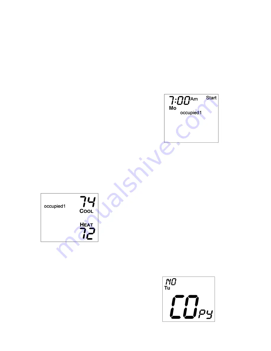
7. The Start Time for Occupied 1 will be displayed. Use the
UP ARROW and DOWN ARROW buttons to raise or
lower the time until the desired Start Time is shown. Press
the Mode button to continue. See Fig. 7.
8. The Stop Time for Occupied 1 will be displayed. Use the
UP ARROW and DOWN ARROW buttons to raise or
lower the time until the desired Stop Time is shown. Press
the Mode button to continue.
9. The On/Off icon will be displayed. Use the UP ARROW
to turn the Occupied 1 period ON for this day. Use the
DOWN ARROW to turn the Occupied 1 period OFF for
this day.
10. If more than one occupied period has been selected in
Step 1, repeat Steps 2 through 9 to program the remaining
schedule for Occupied periods 2 and 3.
11. The Copy command can be used to copy the previous
day’s schedule if the schedules are the same. The copy
command becomes available after all the occupied peri-
ods are programmed in a day. Use the UP ARROW to
change the copy command to YES. Use the DOWNAR-
ROW to change the copy command to NO. Press the
Mode button when the choice has been made. See Fig. 8.
If NO was selected, the schedule will automatically
change to the next day and the user must enter the occu-
pied schedules for that day.
NOTE: Occupied 1 schedule heating and cooling set
points are the same for each day. Occupied 2 and 3 set
points may be set to different values for each day of the
week.
Fig. 6 — Setting Occupied 1 Set Points
Fig. 7 — Start Time Display
Fig. 8 — Copy Command Display
105
→
Summary of Contents for DEBONAIR 33CS
Page 11: ......


