background image

34

11 - STANDARD MAINTENANCE

Air conditioning equipment must be maintained by profes-sional 

technicians, whilst routine checks can be carried out locally by 

specialised technicians. See the standard EN 378-4.
Simple preventive maintenance will allow you to get the best 

performance from your HVAC unit:


-

improved cooling performance


-

reduced power consumption


-

prevention of accidental component failure


-

prevention of major time-consuming and costly inter-

ventions


-

protection of the environment

There are five maintenance levels for HVAC units, as defined by 

the AFNOR X60-010 standard.

11.1 - Level 1 maintenance (see note)

Simple procedure can be carried out by the user:


-

Visual inspection for oil traces (sign of a refrigerant leak)


-

Air heat exchanger (condenser) cleaning - see chapter 

“Condenser coil - level 1”


-

Check  for  removed  protection  devices,  and  badly  closed 

doors/covers


-

Check the unit alarm report when the unit does not work (see 

report in the 30XA/30XAS/30XW Touch Pilot control manual).

General visual inspection for any signs of deterioration.

11.2 - Level 2 maintenance (see note)

This level requires specific know-how in the electrical, hydraulic 

and mechanical fields. It is possible that these skills are available 

locally:  existence  of  a  maintenance  service,  industrial  site, 

specialised subcontractor.

In  these  cases,  the  following  maintenance  operations  are 

recommended.

Carry out all level 1 operations, then:  


-

At least once a year tighten the power circuit electrical 

connections (see tightening torques table).


-

Check  and  re-tighten  all  control/command  connections,  if 

required (see tightening torques table).


-

Remove the dust and clean the interior of the control boxes, 

if required.


-

Check the presence and the condition of the electrical 

protection devices.


-

Check the correct operation of all heaters.


-

Replace the fuses every 3 years or every 15000 hours (age-

hardening).


-

Replace the control box cooling fans used with option 22 

(with designation EF22_) every five years.


-

Check the height of the anti-vibration mountings (located 

between the compressor rails and the unit chassis) after 5 

years  of  operation,  and  then  each  year.  When  the  total 

minimum height of the mountings is less than 25 mm replace 

the mountings.


-

Check the water connections.


-

Purge  the  water  circuit  (see  chapter  “Water  flow  control 

procedure”).


-

Clean the water filter (see chapter “Water flow control 

procedure”).


-

Fully  clean  the  condensers  with  a  low-pressure  jet  and  a 

bio-degradable cleaner (counter-current cleaning - see 

chapter “Condenser coil - level 2).


-

Replace the stuffing box packing of the pump after 10000 

hours of operation.


-

Check the unit operating parameters and compare them with 

previous values.


-

Keep and maintain a maintenance sheet, attached to each 

HVAC unit.


-

Check correct operation of the capacitor (power factor 

correction option 231).

All these operations require strict observation of adequate safety 

measures:  individual  protection  garments,  compliance  with  all 

industry regulations, compliance with applicable local regulations 

and using common sense. 

11.3 - Level 3 (or higher) maintenance (see 

note)

The  maintenance  at  this  level  requires  specific  skills/approval/

tools and know-how and only the manufacturer, his representative 

or authorised agent are permitted to carry out these operations. 

These maintenance operations concern for example:


-

A major component replacement (compressor, evaporator)


-

Any intervention on the refrigerant circuit (handling refrigerant)


-

Changing of parameters set at the factory (application 

change)


-

Removal or dismantling of the HVAC unit


-

Any intervention due to a missed established maintenance 

operation


-

Any intervention covered by the warranty

NOTE: Any deviation or non-observation of these maintenance 

criteria will render the guarantee conditions for the HVAC unit 

nul and void, and the manufacturer, Carrier France, will no 

longer be held responsible.
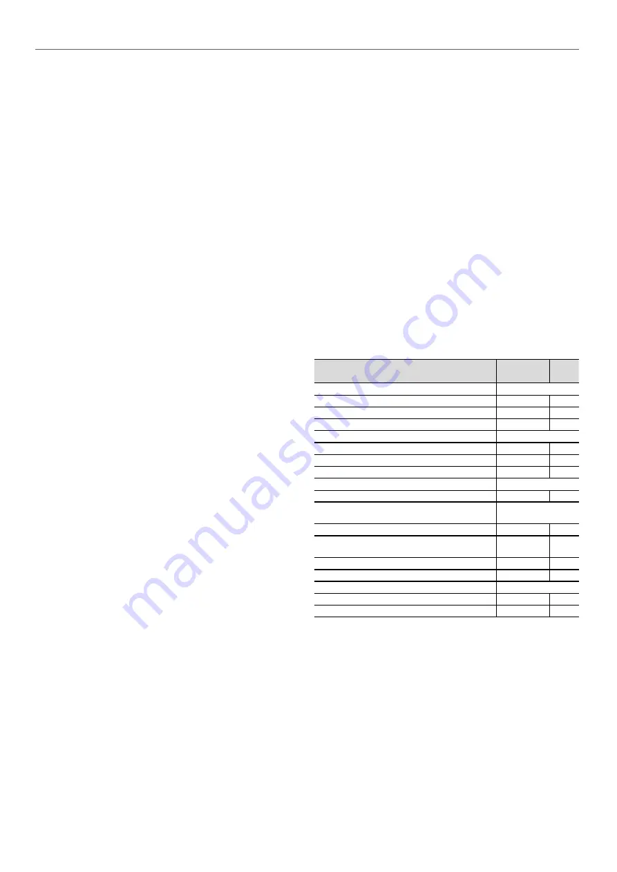
11.4 - 

Tightening torques for the main electrical 

connections

Component

Designation 

in the unit

Value

(N·m)

Screw on bus bar, customer connection

M8

-

18

M10

L1 /L2 /L3

30

Soldered screw PE, customer connection (M12)

PE

70

Tunnel terminal screw, compressor contactor

Contactor 3RT104_

-

5

Contactor  3RT105_

-

11

Contactor  3RT106_

KM_

21

Tunnel terminal screw, current transformer

Size 2 (3RB2956_)

-

11

Compressor earth terminal in the power wiring 

control box
Terminal M8

Gnd

30

Compressor phase connection terminals M12

1 /2 /3 /4 /5 

/6 sur EC_

25

Compressor earth connection

Gnd sur EC_

25

Tunnel terminal screw, disconnects 3RV1011_

QF_ /QM_

1

Tunnel terminal screw, hydraulic pump contactor

Contactor 3RT101_

KM90_

1

Contactor 3RT102_

-

2.2

Summary of Contents for Aquaforce 30XAS Series

Page 1: ...LLATION OPERATION AND M A I N T E N A N C E I N S T R U C T I O N S Original document Air Cooled Liquid Chillers 30XAS A Unit with option 279 compressor enclosure Nominal cooling capacity 232 486 kW 5...

Page 2: ...2...

Page 3: ...entry 17 5 5 Field control wiring 17 6 APPLICATION DATA 18 6 1 Operating range 18 6 2 Minimum chilled water flow units without hydraulic module 18 6 3 Maximum chilled water flow units without hydrauli...

Page 4: ...maintenance see note 34 11 2 Level 2 maintenance see note 34 11 3 Level 3 or higher maintenance see note 34 11 4 Tightening torques for the main electrical connections 34 11 5 Tightening torques for...

Page 5: ...or ice These devices as well as the drain piping must not impair operation and not lead to a pressure drop that is higher than 10 of the control pressure Classification and control In accordance with...

Page 6: ...ed off the power circuit remains energized unless the unit or circuit disconnect switch is open Refer to the wiring diagram for further details Attach appropriate safety labels Units with option 231 a...

Page 7: ...f a leak occurs or if the refrigerant becomes contaminated e g by a short circuit in a motor remove the complete charge using a recovery unit and store the refrigerant in mobile containers Repair the...

Page 8: ...uit Do not attempt to repair or recondition any safety devices when corrosion or build up of foreign material rust dirt scale etc is found within the valve body or mechanism If necessary replace the d...

Page 9: ...e frequency number of phases Maximum current drawn Maximum power input Unit net weight Confirm that all accessories ordered for on site installation have been delivered and are complete and undamaged...

Page 10: ...than 15 WARNING Never push or lever on any of the enclosure panels of the unit Only the base of the unit frame is designed to withstand such stresses 2 2 3 Checks before system start up Before the st...

Page 11: ...ional drawings supplied with the unit or available on request For the positioning of the fixing points weight distribution and centre of gravity coordinates please refer to the dimensional drawings B...

Page 12: ...or evaporator tube removal Water inlet Water outlet Air outlet do not obstruct Power supply connection C Control circuit connection 3 4 Multiple chiller installation It is recommended to install multi...

Page 13: ...4798 4798 Width mm 2253 2253 2253 2253 2253 Height mm 2322 2322 2322 2322 2322 Operating weight 4 Standard unit kg 2375 2791 2847 3603 3689 Standard unit option 119 kg 3051 3167 3963 4119 Standard uni...

Page 14: ...15 7 15 7 15 7 Evaporator Flooded multi pipe type Water content l 53 53 53 75 75 Without hydraulic module Water inlet outlet connections Victaulic Nominal diameter in 5 5 5 5 5 Actual outside diamete...

Page 15: ...full load and nominal voltage 88 1 89 4 90 1 91 3 1 Nominal efficiency at 75 rated load and nominal voltage 88 88 9 89 7 91 4 1 Nominal efficiency at 50 rated load and nominal voltage 86 1 86 7 87 9 9...

Page 16: ...60364 Outdoor installation Ambient temperature range from 20 C to 55 C Altitude less than or equal to 2000 m for hydraulic module see paragraph 4 3 in the IOM Presence of hard solids class AE3 no sign...

Page 17: ...ter the control box from below or from the unit side For 30XAS unit sizes 282 to 482 the control box that includes the power supply cable connection terminal is located in the lower part of the unit I...

Page 18: ...peration 3 3 15 Note If the leaving water temperature is below 4 C a glycol water solution or the frost protection option must be used Condenser air temperature C Minimum Maximum Storage 20 68 Operati...

Page 19: ...chieve the required volume The tank must itself be internally baffled in order to ensure proper mixing of the liquid water or brine Refer to the examples below Connection to a buffer tank Bad Bad Good...

Page 20: ...e eletrolytic pairs and consequently corrosion Verify then the need to install sacrificial anodes In case additives or other fluids than those recommended by Carrier are used ensure that the fluids ar...

Page 21: ...lable pressure pump 5 Drain valve 6 Flow control valve 7 Evaporator 8 Evaporator defrost heater option 9 Hydraulic module defrost heater option 10 Air vent evaporator 11 Water drain evaporator 12 Expa...

Page 22: ...in the operating limit table application data 7 5 2 Optional evaporator frost protection 30XAS If it is not possible to apply the recommendations in para graph 7 5 1 the units can be equipped with hea...

Page 23: ...0 350 400 3 5 7 9 11 13 15 17 19 21 23 25 27 29 31 282 3 50 100 150 200 250 300 350 400 5 7 9 11 13 15 17 19 21 23 25 27 29 31 342 442 482 7 7 2 NPSH Net Positive Suction Head required option 116C hyd...

Page 24: ...installed but supplied with the unit The sealing joints are in the control box The temperature sensors and the condenser flow switch are wired and fixed in the machine They must be installed as descri...

Page 25: ...r 8 4 Condenser water connections NOTE Drawings are not contractually binding Before designing an installation consult the certified dimensional drawings supplied with the unit or available on request...

Page 26: ...temperature at start up 12 5 1 55 Water entering temperature during operation 20 55 Water leaving temperature during operation 25 60 Evaporator water temperature C Minimum Maximum Water entering temp...

Page 27: ...eat exchange at the air condenser to heat exchange at the water condenser and vice versa is ensured by motorised two way valves located upstream of the air and water condensers ATTENTION Mode changes...

Page 28: ...eat exchange fluid check and carry out internal inspections as described in EN 378 annex C In case of re testing please refer to the maximum operating pressure given on the unit nameplate The reports...

Page 29: ...6 mm Insert this tool into the opening on the pressure switch and push the reset button in this location These pressure switches are located at the discharge of each compressor 9 3 2 Relief valves 30X...

Page 30: ...n insufficient charge or non con densables in the system The presence of moisture changes the colour of the indicator paper in the sight glass 9 8 Filter drier The role of the filter drier is to keep...

Page 31: ...t 1 2 3 4 1 2 4 5 3 1 2 4 5 3 1 2 5 6 3 6 7 4 1 2 5 6 3 7 4 8 x x Start up order Power connection NOTE The values above do not correspond to the fan designation The fan designation and position are gi...

Page 32: ...ified service and maintenance 30XAS 242 482 Compressor discharge valves 93A Shut off valve on the compressor discharge piping Simplified maintenance 30XAS 242 482 HP dual pump hydraulic module 116C Co...

Page 33: ...corrosive environments 30XAS 242 482 Super Enviro Shield anti corrosion protection 263 Extremely durable and flexible epoxy polymer coating applied on micro channel heat exchangers by electro coating...

Page 34: ...replace the mountings Check the water connections Purge the water circuit see chapter Water flow control procedure Clean the water filter see chapter Water flow control procedure Fully clean the conde...

Page 35: ...with clean water For coils installed in a coastal or industrial environment periodical cleaning by rinsing with water is beneficial It is however essential that rinsing is done with a low speed water...

Page 36: ...mpressor terminal pin as originally wired For replacement of the compressor a low pressure switch is included with the compressor This low pressure switch should be temporarily installed as a hard saf...

Page 37: ...of the unit can be recycled for another purpose 12 3 Fluids to be recovered for treatment Refrigerant Heat transfer fluid depending on the installation water brine solution etc Compressor oil 12 4 Ma...

Page 38: ...otection has been sized and installed properly All terminals are tight All chilled water valves are open All chilled water piping is connected properly All air has been vented from the chilled water c...

Page 39: ...y supply at once and ensure that the chiller is not switched on until corrective measures have been taken Check cooler water loop Water loop volume litres Calculated volume litres 3 25 litres nominal...

Page 40: ...alidity of certificate www eurovent certification com Order No 13467 09 2018 Supersedes order No 13467 12 2016 Manufactured by Carrier SCS Montluel France Manufacturer reserves the right to change any...

Reviews: