


Packaged rooftop units
27
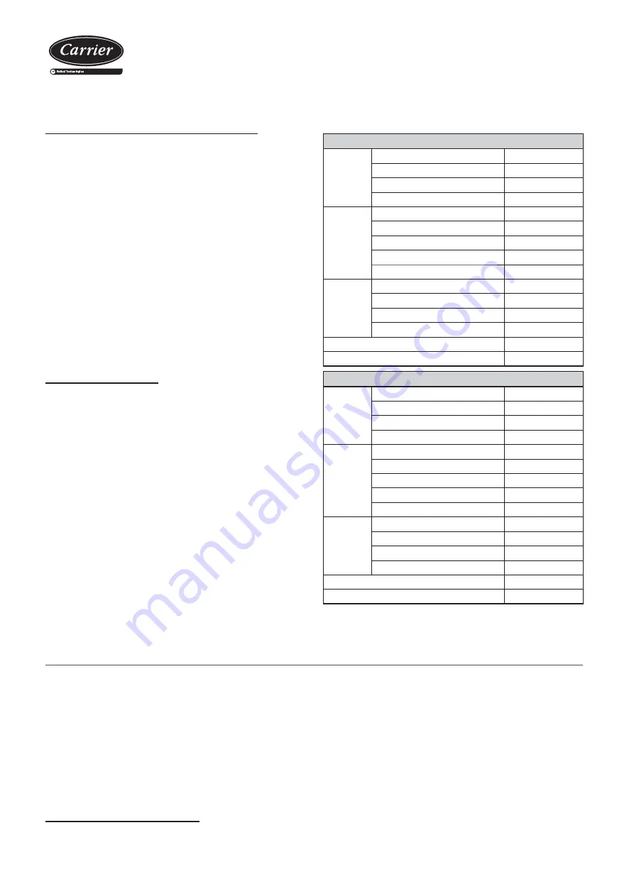
Cooling MODE
Compressor
Suction pressure
bar
Suction temperature (1)
ºC
Condensation pressure
bar
Condensation temperature (2)
ºC
Air
condenser
Gas inlet temperature
ºC
Liquid outlet temperature (3)
ºC
Air inlet temperature
ºC
Outdoor temperature
ºC
Air outlet temperature
ºC
Air
evaporator
Air inlet temperature
ºC
Air outlet temperature
ºC
Liquid inlet temperature
ºC
Evaporation outlet temperature (4) ºC
Subcooling (2) - (3)
ºC
Overheating (4) - (1)
ºC
Heating MODE
Compressor
Suction pressure
bar
Suction temperature (1)
ºC
Condensation pressure
bar
Condensation temperature (2)
ºC
Air
evaporator
Liquid inlet temperature
ºC
Gas outlet temperature (4)
ºC
Air inlet temperature
ºC
Outdoor temperature
ºC
Air outlet temperature
ºC
Air
condenser
Air inlet temperature
ºC
Air outlet temperature
ºC
Gas inlet temperature
ºC
Liquid outlet temperature (3)
ºC
Subcooling (2) - (3)
ºC
Overheating (4) - (1)
ºC
13. M
AINTENANCE
The minimal maintenance operations and their periodicity will be made
according to the national regulations.
Any intervention on the electric cooling components must be made by
a quali
fi
ed and authorized technician.
Technicians who intervene with the unit must use the necessary safety
equipment (gloves, goggles, insulating clothing, safety shoes, etc.).
Furthermore, if working around sources of significant noise, we
recommend the use of noise-dampening headgear.
General recommendations
- Do not lean on the unit. A platform must be used to work on a level.
- Do not lean on the copper refrigerant tubes.
- Keep the unit clean.
- Keep the space surrounding the unit clean and cleared in order to
avoid accidents and ensure the proper ventilation of the coil.
- Perform a visual (remains of water or oil below or around the unit)
and auditory inspection of the entire installation.
- In general, a corrosion control must be performed on the metallic
parts of the unit (frame, bodywork, exchangers, electric panel, etc.).
- Check that the insulation foam is not unstuck or torn.
- All the electric connection states must be checked as well, as well
as the air tightness of the different circuits.
Check the unit operation by verifying the electronic control and the
safety devices.
It is also recommendable to create a report, taking note of the date,
which includes the following information:
- the nominal voltage,
- current absorbed by the compressors, fans and other electrical
components,
- signi
fi
cant temperatures in the cooling circuit (see attached table),
- other aspects considered interesting such as alarms detected by the
electronic control of the unit.
The recording of these parameters whilst the unit is running allows
controlling the installation performance and it is the best possible way
to avoid breakdowns since the analysis of these data makes early
detection of anomalies possible or the provision of the necessary means
available to ensure that they do not take place.
Operational checks
Possible problems at commissioning
All indications given in this brochure must be respected and
complied with to guarantee a correct operation of the units.
Next, several possible operation problems are stated which could
happen if the conditions of the commissioning are not appropriate.
- Air flow lack: very high differences between inlet and outlet
temperatures, originated by a high pressure drop in the ducts, or by
other causes that impede the correct circulation.
- Air recirculation in the unit, originated by some obstacle in the air
aspiration or outlet.
- Noise problems because of excessive air
fl
ow in the grille.
- Water over
fl
owing to the pan problems, originated by an excessive
fl
ow, an incorrect siphon installation or because a defective unit level.
- Refrigerant circuit humidity problem, because of an incorrect vacuum
realization.
Summary of Contents for 50EH
Page 34: ...Packaged rooftop units 34 Notes...
Page 35: ......


