


Coil Freeze-Up Protection
WATER COILS — If a chilled water coil is applied with
outside air, provisions must be made to prevent coil freeze-
up. Install a coil freeze-up thermostat to shut down the sys-
tem if any air temperature below 36 F is encountered enter-
ing the water coil. Follow thermostat manufacturer’s
instructions.
When a water coil is applied downstream of a direct-
expansion (DX) coil, a freeze-up thermostat must be in-
stalled between the DX and water coil and electrically in-
terlocked to turn off the cooling to prevent freeze-up of the
water coil.
For outdoor-air application where intermittent chilled
water coil operation is possible, one of the following steps
should be taken:
• Install an auxiliary blower heater in cabinet to maintain above-
freezing temperature around coil while unit is shut down.
• Drain coils and fill with an ethylene glycol solution suit-
able for the expected cold weather operation.
• Shut down the system and drain coils. See Service section,
Winter Shutdown, page 75.
STEAM COILS — When used for preheating outdoor air in
pressure or vacuum systems, an immersion thermostat to con-
trol outdoor-air damper and fan motor is recommended. This
control is actuated when steam supply fails or condensate
temperature drops below an established level, such as 120 to
150 F. A vacuum breaker should also be used to equalize
coil pressure with the atmosphere when steam supply throttles
close. Steam should not be modulated when outdoor air is
below 40 F.
On low-pressure and vacuum steam-heating systems, the
thermostat may be replaced by a condensate drain with a
thermal element. This element opens and drains the coil when
condensate temperature drops below 165 F. Note that con-
densate drains are limited to 5 psig pressure.
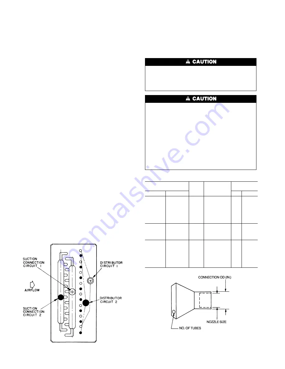
Refrigerant Piping, Direct-Expansion Coils —
See Fig. 43. Direct-expansion (DX) coils are divided into 2
or 4 splits depending upon the unit size and coil circuiting.
Each split requires its own distributor nozzle, expansion valve,
and suction piping. Suction connections are on the air en-
tering side when the coil is properly installed. Matching dis-
tributor connections for each coil split are on the air leaving
side. See unit label or certified drawing to assure connection
to matching suction and liquid connections.
Table 19 shows distributor part numbers. Table 20 shows
DX coil circuiting data.
NOTE: Distributor nozzles are factory selected and installed
for adequate performance in many unit applications. For best
performance, use Carrier’s AHU Builder™ program to se-
lect nozzle sizes for each unit and replace the factory-
installed nozzles as required. See the Thermostatic Expan-
sion Valve Piping section on page 59 for further details.
To prevent damage to the coil or coil headers: Do not
use the headers to lift the coil. Support the piping and
coil connections independently. Do not use the coil con-
nections to support piping. When tightening coil con-
nections, use a backup wrench on the stub outs.
Direct-expansion coils are shipped pressurized with dry
air. Release pressure from each coil split through valves
in protective caps before removing caps.
Do not leave piping open to the atmosphere unnec-
essarily. Water and water vapor are detrimental to the
refrigerant system. Until the piping is complete, recap
the system and charge with nitrogen at the end of each
workday. Clean all piping connections before soldering
joints.
The lower split of face split coils should be first on,
last off.
Row split coils utilize special intertwined circuits (as
shown in Fig. 43); either split of these row split coils
can be first on, last off.
Table 19 — Distributor Part Numbers
PART NO.
NO.
OF
TUBES
CONNECTION
OD (in.)
SPORLAN
NOZZLE
Sporlan
Carrier
Type
Size
1112-2-
1
⁄
4
EA07NC261
2
0.88
G
3
⁄
4
to 12
1112-3-
1
⁄
4
EA07FC027
3
1112-4-
1
⁄
4
EA07NC262
4
1112-5-
1
⁄
4
EA07NC263
5
1112-6-
1
⁄
4
EA07NC264
6
1113-7-
1
⁄
4
EA07HC207
7
1113-8-
1
⁄
4
EA07HC208
8
1115-8-
1
⁄
4
EA07KC240
8
1.12
E
3 to 30
1115-9-
1
⁄
4
EA07KC241
9
1115-10-
1
⁄
4
EA07KC242
10
1116-11-
1
⁄
4
EA07HC011
11
1117-11-
1
⁄
4
EA07LC510
11
1.38
C
3 to 50
1117-12-
1
⁄
4
EA07HC012
12
1117-13-
1
⁄
4
EA07HC013
13
1126-14-
1
⁄
4
EA07TC290
14
1126-15-
1
⁄
4
EA07HC015
15
1126-16-
1
⁄
4
EA07TC207
16
1126-17-
1
⁄
4
EA07HC017
17
Fig. 43 — Typical Direct-Expansion Row Split Coil
50
Summary of Contents for 39T
Page 43: ...Fig 34 Discharge Fabrication Draw Thru Plenum Fans 43 ...
Page 49: ...Fig 41 Coil Connections and Lifting Points Fig 42 Steam Coil PIping 49 ...
Page 78: ...Fig 64 Blow Thru Unit Coil Removal Fig 65 Plan View Typical Coil 78 ...
Page 81: ...Fig 68 Filter Arrangement 2 in and 4 in Flat 81 ...
Page 82: ...Fig 68 Filter Arrangement 2 in and 4 in Flat cont 82 ...
Page 83: ...Fig 69 Filter Arrangement Angle Filters 2 in Only 83 ...
Page 84: ...Fig 69 Filter Arrangement Angle Filters 2 in Only cont 84 ...
Page 85: ...Fig 70 Filter Arrangement BCF1 Bag or Cartridge Draw Thru 85 ...
Page 86: ...Fig 70 Filter Arrangement BCF1 Bag or Cartridge Draw Thru cont 86 ...
Page 87: ...Fig 71 Filter Arrangement BCF3 Bag or Cartridge Blow Thru 87 ...
Page 88: ...Fig 71 Filter Arrangement BCF3 Bag or Cartridge Blow Thru cont 88 ...
Page 92: ...NOTE A frame shown shaded Fig 74 Fan Discharge Positions 92 ...
Page 102: ......
Page 103: ......


