background image

15

For normal maintenance routines we recommend using 1 kg of
the concentrated product, diluted to 10%, to treat a coil surface
of  2 m

2

This process can either be carried out with a

TOTALINE applicator gun (part No. TE01 WA 4000EE) or
using a high-pressure spray gun in the low-pressure position.
With pressurised cleaning methods care should be taken not to
damage the coil fins.

The spraying of the coil must be done:
- in the direction of the fins
- in the opposite direction of the air flow direction
- with a large diffuser (25-30

°

)

- at a distance of 300 mm.

The two cleaning products can be used for any of the following
coil finishes: Cu/Cu, Cu/Al, Cu/Al with Polual, Blygold and/or
Heresite protection.

It is not necessary to rinse the coil, as the products used are pH
neutral. To ensure that the coil is perfectly clean, we
recommend rinsing with a low water flow rate. The pH value
of the water used should be between 7 and 8.

WARNING: Never use pressurized water without a large
diffusor. Concentrated and/or rotating water jets are strictly
forbidden.

Correct and frequent cleaning (approximately every three
months) will prevent 2/3 of the corrosion problems.

WARNING: Never use pressurized air or water, as this will
damage the fins, and always clean them against the normal air
flow direction.

Fan motor replacement

38AJ/AZ 008-012 units
Follow the safety considerations. Fan motors can be easily
removed through the top of the unit. Take care not to damage the
propeller. Label the wires to facilitate correct reassembly later.
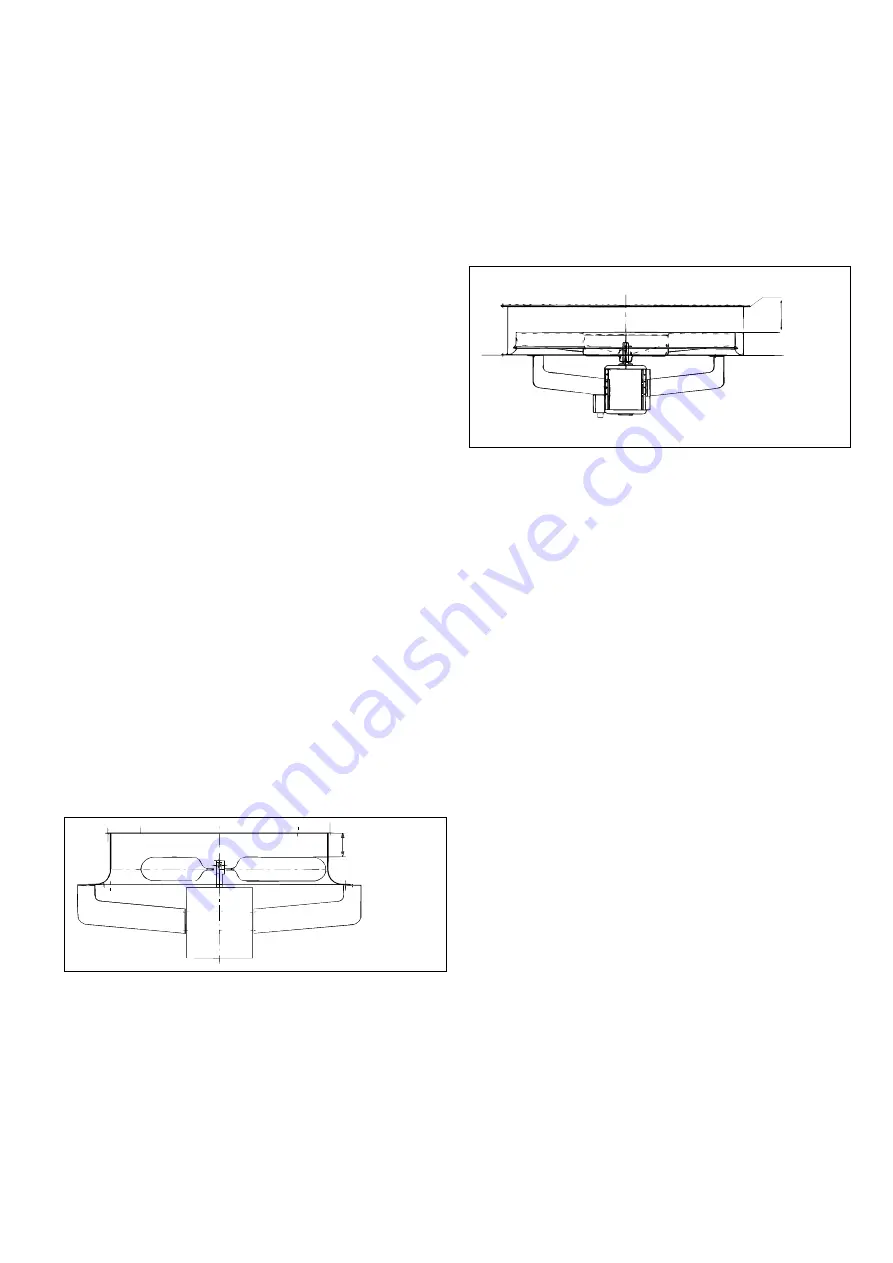
38AJ/AZ 008-012 fan

Maximum
clearance

80 mm +    mm

0
2

Maximum
clearance

170 +   mm

0
2

38AJ/AZ 018-024 units
This presents no special problems. The work is done from
above the unit.

Remove the grille with its support air duct assembly.

Remove the fan shaft protection cap.

Pull the fan from the shaft using a FACOM U35, or
similar, hub puller.

Unscrew the fan motor fixing bolts.

WARNING: Remove only the lower bolts to prevent the
motor from falling.

Fan motor protection
All fan motors have thermal protection which will stop the
current flow when the fan motor temperature becomes too
high. The fans will restart automatically when the motor
temperature drops to a safe level. In addition all fan motors are
protected by one or several circuit breakers.

Refrigerant circuit

Liquid line service valve
This valve provides, in each circuit, a liquid refrigerant charging
port and, in conjunction with the compressor discharge line
valves, enables liquid refrigerant to be pumped to the high
pressure side of the system.

Withdraw the fan motor.

Installation is in the reverse order. Take care not to damage the
plastic components when installing the fan and position the fan
to maintain a clearance of 170 + 0/2 mm between the upper
edge of the fan and the upper edge of the volute. The tightening
torque on the fan motor support fixing screws must be 9 Nm.

CAUTION: On unit sizes 38AJ/AZ 014-074 the fan rotation is
counter clockwise, viewed from above.

38AJ/AZ 014-074 fan

Summary of Contents for 38AJ 008

Page 1: ...1 QUALITY ASSURANCE SYSTEM 38AJ 008 074 R 22 38AZ 008 074 R 407C Air Cooled Condensing Units 50 Hz Installation Operation and Maintenance Instructions...

Page 2: ...trol systems 11 Pressure operated control valve 11 Control setpoint 11 Setpoint control 11 Pressure differential 12 Modifications 12 Servicing refrigeration components 13 General maintenance 13 Liquid...

Page 3: ...gas pressure kPa Pressure drop air kPa Circuit 2 Suction gas temperature C Discharge air pressure Pa Suction gas pressure kPa Fan speed r s or rpm Fan motor input Ph 1 V Ph 2 V Ph 3 V Ph 1 V Ph 2 V P...

Page 4: ...70 1912 2500 1200 500 1200 062 074 2900 2156 2060 2500 1200 500 1200 Legend All dimensions are given in mm Required clearance space for servicing Power supply Water inlet Water outlet Do not obstruct...

Page 5: ...unit These units are designed for outdoor installation CAUTION Ensure the air flow around the unit is not obstructed At least two sides of the units must be free from obstructions to ensure proper ai...

Page 6: ...n dew point temperature R 407C of 10 C saturated discharge temperature R 22 or discharge dew point temperature of 68 3 C ICF maximum instantaneous current during starting equal to the current value of...

Page 7: ...unit Moving Do not remove skids pallets or protective packaging until the unit is in its final position Move the chiller using tubes or rollers or lift it using slings of the correct capacity Siting B...

Page 8: ...sure Legend 1 Condenser 2 Liquid line valve 3 Filter drier 4 Sight glass 5 Fan cycling pressure switch 6 Suction valve NOTE The typical refrigeration circuit diagram shown does not apply to all contro...

Page 9: ...tions to accomplish this Bypass hot gas if used should be introduced before the evaporator Consult your local Carrier distributor The oil charge must be adjusted to allow for extra line length This is...

Page 10: ...tions use the piping shown for the upper and the middle sections 3 The lower section is always the first section to be activated and the last to be shut off 4 Refer to the Carrier System Design Manual...

Page 11: ...ergized when the unit is switched off to ensure proper lubrication of the compressor Open the compressor suction and discharge line valves and then close them one turn each to stabilise the pressure t...

Page 12: ...Pressure operated control valve Modifications It is possible to convert pressure controlled capacity reductions to electrically controlled reductions or to add capacity reductions in accordance with t...

Page 13: ...es Refrigeration installations must be inspected and maintained regularly and rigorously by specialists Their activities must be overseen and checked by properly trained people To minimise discharge t...

Page 14: ...hen to ON NOTE Damage resulting from failure to follow these instruction is not covered by the product warranty Compressor motor protection Compressor protection devices Circuit breaker Calibrated the...

Page 15: ...y removed through the top of the unit Take care not to damage the propeller Label the wires to facilitate correct reassembly later 38AJ AZ 008 012 fan Maximum clearance 80 mm mm 0 2 Maximum clearance...

Page 16: ...strainer Check valve plates for valve noise Replace compressor worn bearings Check for loose compressor hold down bolts Find and repair leak pump down and recharge Replace heaters check wiring Adjust...

Reviews: