background image

22

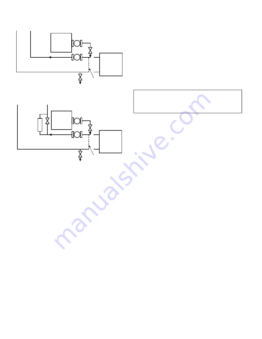
Also, be sure that there is capability to fully drain the system

after cleaning. (See Fig. 23 and 24.)

Fig. 23 — 

Typical Set-up for Cleaning Process

Fig. 24 — 

Cleaning Process Using Side Stream Filter

2. Be sure to use a cleaning agent that is compatible with all sys

-

tem materials.  Be  especially  careful  if the system  contains

any  galvanized  or  aluminum  components.  Both  detergent-

dispersant and alkaline-dispersant cleaning agents are avail

-

able.

3. It is a good idea to fill the system through a water meter. This

provides  a  reference  point  for  the  future  for  loop  volume

readings, and it also establishes the correct quantity of cleaner

needed in order to get the required concentration.

4. Use a feeder/transfer pump to mix the solution and fill the

system. Circulate the cleaning system for the length of time

recommended by the cleaning agent manufacturer.
 a. After cleaning, drain the cleaning fluid and flush the sys

-

tem with fresh water.

 b. A slight amount of cleaning residue in the system can

help keep the desired, slightly alkaline, water pH of 8 to

9. Avoid a pH greater than 10, since this will adversely

affect pump seal components.

 c. A side stream filter is recommended (see Fig. 24) during

the  cleaning  process.  Filter  side  flow  rate  should  be

enough  to  filter  the  entire  water  volume  every  3  to  4

hours.  Change  filters  as  often  as  necessary  during the

cleaning process.

 d. Remove temporary bypass when cleaning is complete.

Properly  installed  and  cleaned  systems  will  rarely  need  the

strainer cleaned after the initial fill. This time interval is user-

configurable.
WATER TREATMENT
Fill the fluid loop with an inhibited antifreeze solution suitable for

the water of the area. The solution concentration must be sufficient

to protect the chilled water loop to a freeze protection (first crys

-

tals) concentration of at least 15°F (8.3°C) below the lowest de

-

sign ambient temperature. Consult the local water treatment spe

-

cialist for characteristics of system water and a recommended in

-

hibitor for the fluid loop.

Untreated or improperly treated fluid may result in corrosion, scal

-

ing, erosion, or algae. The services of a qualified water treatment

specialist should be obtained to develop and monitor a treatment

program.
FILLING THE SYSTEM
In areas where the piping or unit is exposed to 32°F (0°C) or lower

ambient temperatures, freeze-up protection is required using in

-

hibited glycol or other suitable, heat exchanger rated, corrosion-re

-

sistant antifreeze solution. Heater tapes cannot be installed on the

coils and heater tape on piping will not provide any protection. 

NOTE: Do not use automobile antifreeze, or any other fluid that is

not approved for heat exchanger duty. Only use appropriately in

-

hibited glycols, concentrated to provide  adequate protection for

the temperature considered.

If the unit is in operation year-round, add sufficient suitable inhib

-

ited antifreeze solution such as propylene or ethylene glycol to

chilled water to prevent freezing under low-ambient temperature

operating conditions. Consult a local water treatment specialist on

characteristics of water and recommended inhibitor.

The initial fill of the fluid system must accomplish three purposes:

• The  entire  piping system  must  be  filled  with water/anti

-

freeze solution.

• The pressure at the top of the system must be high enough

to vent air from the system (usually 4 psig [28 kPa] is ade

-

quate for most vents).

• The  pressure  at  all  points  in  the  system  must  be  high

enough to prevent flashing in the piping or cavitation in

the pump.

Ensure the following when filling the system:

1. Remove  temporary  bypass  piping  and  cleaning/flushing

equipment.

2. Check to make sure all drain plugs are installed.
3. Vents (if installed) at the top of the coils should be open.
4. Open the blow-down valve to flush the strainer.
5. Check for fluid leaks and repair as necessary.
Normally, a closed system needs to be filled only once. The actual

filling  process  is  generally  a  fairly  simple  procedure.  All  air

should be purged or vented from the system. Thorough venting at

the high points at the top of all coils and circulation at room tem

-

perature for several hours is recommended.

NOTE: Local codes concerning backflow devices and other pro

-

tection of the city water system should be consulted and followed

to prevent contamination of the public water supply. This is espe

-

cially important when antifreeze is used in the system.
SET WATER FLOW RATE 
Once the system is cleaned, pressurized, and filled, the  flow

rate must be set. Set the flow rate per the chiller instructions.

The chiller flow is critical for correct performance and reliabil

-

ity. The 09FC is less sensitive to off design flow rates. Flow

-

rate  should  be  set  with the  09FC unit  in  free cooling  mode.

This  mode  will  have  a  larger  pressure  drop  than  the  bypass

mode. Setting the flow in this mode assures the chiller will al

-

ways have the minimum flow required for operation.

x

x

DILUTED

CLEANING

AGENT

SYSTEM

POT FEEDER AND
TRANSFER PUMP

UNIT 

TO DRAIN

TEMPORARY
 PUMP

TEMPORARY
BYPASS

x

x

DILUTED

CLEANING

AGENT

SYSTEM

SIDE
STREAM
FILTER

POT FEEDER AND
TRANSFER PUMP

UNIT 

TO DRAIN

TEMPORARY
 PUMP

TEMPORARY
BYPASS

IMPORTANT: Adding antifreeze solution is the only cer

-

tain means of protecting the unit from freeze-up since heat

-

ers cannot protect the coils while temperatures are below

32°F (0°C).

Summary of Contents for 09FC020

Page 1: ...ART SNOW CLEARING START UP 53 SERVICE 53 Alarms 53 NON OPERATIONAL COMPONENT ALARM REVERSE LOAD WATER FLOW ALARM THERMISTOR ALARM FAN VFD FAILURE Alarm Troubleshooting 54 LEAVING WATER TEMPERATURE ALA...

Page 2: ...been given instruction DANGER Electrical shock can cause personal injury and death After unit power is disconnected wait at least 20 minutes for the Variable Frequency Drives VFD capacitors to discha...

Page 3: ...itrogen Shipping Charge 5 psig Fans and Motors Shrouded Axial Type Vertical Discharge Quantity 4 6 8 10 12 14 16 Maximum Speed rpm r s 1140 19 Coils Type Round Tube Plate Fin No of Coils 4 6 8 10 12 1...

Page 4: ...at Cu Tube Al Fin Not Used Not Used Piping Valve Options 3 way Valves Electrical Options 0 Single Point Power Fused Disconnect High SCCR Control Options BACNet Shipping Options 0 Coil Covers 1 Coil Co...

Page 5: ...922 1069 916 1063 884 1069 932 1127 Table 3 Unit Operating Corner Weights kg UNIT SIZE OPERATING WEIGHT AT CORNER WEIGHTS LBS A B C D E F G H 020 450 516 456 523 030 639 754 643 758 040 433 501 418 4...

Page 6: ...consists of coil protection only Skids are not provided unless selected as a shipping option If overhead rigging is not available at the jobsite the unit should be placed on a skid or pad before drag...

Page 7: ...ove the top of the unit and coils 5 If overhead rigging is not available the unit can be moved on roller or dragged When unit is moved on roller the unit steel skid if equipped must be removed To lift...

Page 8: ...8 Fig 5 09FC 020 Unit Dimensions...

Page 9: ...9 Fig 6 09FC 030 Unit Dimensions...

Page 10: ...10 Fig 7 09FC 040 Unit Dimensions...

Page 11: ...11 Fig 8 09FC 050 Unit Dimensions...

Page 12: ...12 Fig 9 09FC 060 Unit Dimensions...

Page 13: ...13 Fig 10 09FC 070 Unit Dimensions...

Page 14: ...14 Fig 11 09FC 080 Unit Dimensions...

Page 15: ...supplied See Fig 5 11 Be sure unit is level to within 1 8 in 3 2 mm per foot for factory sup plied drains to operate properly NOTE For units that are point loaded such as those using rubber and shear...

Page 16: ...DE OF UNIT BASE RAIL OUTER SIDE OF UNIT BASE RAIL 0 1 3 4 44 mm 1 50 DIA 38 mm RIGGING HOLE B B 0 5 127 mm 0 875 DIA 22 mm MOUNTING HOLE MOUNTING PLATE 0 3 15 16 100 mm 0 1 9 16 39 89 mm REF 0 7 7 8 2...

Page 17: ...tems equipment should be provided to eliminate all air from the system The amount of air that water can hold in solution depends on the pressure and temperature of the water air mixture Air is less so...

Page 18: ...properly in the bolt hole 7 Tighten the nuts evenly by alternating sides until metal to metal contact occurs at the bolt pads Make sure the housings keys engage the grooves completely NOTE It is impor...

Page 19: ...e reattached add the joining pipe include in the Modular Piping Accessory Part No 09FC70000801 Attach with the existing couplings Add insula tion back to the tees and joining pipe section Fig 18 09FC...

Page 20: ...nimum access is a recommendation Local code may require increased spacing 3 Chiller tube service must be done from control panel end for this arrangement See chiller certified drawings for details 09F...

Page 21: ...ote 2 09FC Control Panel NOTES 1 Allow 36 in for fan VFD access Verify 36 in meets local codes 2 EWT and LWT thermistors must be installed in the field Thermistors are supplied inside control panel Ad...

Page 22: ...y protection NOTE Do not use automobile antifreeze or any other fluid that is not approved for heat exchanger duty Only use appropriately in hibited glycols concentrated to provide adequate protection...

Page 23: ...Rt equals the equivalent pressure drop which R1 and R2 are the individual circuits Curves are for 30 Propylene Glycol PG Use multipliers for other fluids or brine concentration amounts Fig 25 09FC 02...

Page 24: ...FC Mode Bypass Mode GPM ft wc WARNING Electrical shock can cause personal injury and death Shut off all power to this equipment during installation There may be more than one disconnect switch Tag al...

Page 25: ...414 506 4 8 39 6 40 40 575 518 633 3 8 31 4 35 35 380 50 342 418 5 9 48 8 50 50 400 360 440 5 6 46 4 50 50 415 374 456 5 4 44 7 50 50 440 396 480 5 1 42 2 45 45 050 380 60 342 418 10 5 8 59 5 60 60 40...

Page 26: ...ng Manangement System CB Circuit Breaker EWT Entering Water Temperature FU Fuse FM Fan Motor GND Ground IN Thermistor or Dry Contact Input LWT Leaving Water Temperature OAT Outdoor Air Temperature R1...

Page 27: ...ocation of field power entry Be sure to seal entering power wire conduit per NEC requirements 3 Maximum field wire sizes allowed by lugs on fused discon nect are listed in Table 4 4 Terminals for fiel...

Page 28: ...NICATION OPTIONS The 09FC controls can support communication via BACnet ARC156 156 kbps or BACnet MS TP 9600 bps 76 8 kbps Wiring for BACnet communication is at Net Net and Shield at the top left of t...

Page 29: ...upper corner post bolts and slide the baffle un derneath the flange bolt Tighten the bolt Drill holes in the bottom of the flange of the baffle and mount with two screws to secure the bottom to the c...

Page 30: ...er The Carrier AppController is the heart of the control system It contains the operating software and controls the operation of the machine The CarrierAppController software continuously evalu ates i...

Page 31: ...uld be set to the upper position for thermistor IN 5 jumper should be on Fig 33 Carrier AppController Jumper Settings Carrier Equipment Touch Display Equipment touch is the user interface for the Carr...

Page 32: ...evel None Home Click on the right to navigate to Snapshot screen The HOME screen is the main screen Displays Leaving water temperature Outdoor air temperature Operating Mode Run Command Occupancy Pass...

Page 33: ...ic password level are visible Password Level None Properties Status This menu shows the status or value of the listed point Password Level None Properties Unit Configuration Cooling Lockout Default 50...

Page 34: ...0 F hi 245 Range 100 to 245 F Non Operational Comp This drives the Non Operational Component alarm The is the alarm offset value CWST This is a low limit alarm offset Reverse Load Water Flow This alar...

Page 35: ...lect the exclamation point in the top left of the screen from the Snapshot screen Trends NOTE Example screen shown Review trends for points that have trending enabled Access from the Snapshot screen b...

Page 36: ...36 Table 8 App Controller Screen Navigation cont SCREEN NAMES DISPLAY Properties Alarms Alarm Help 11 screens Password Level None...

Page 37: ...ller Screen Navigation cont SCREEN NAMES DISPLAY DETAILS Properties Alarms Alarm History Password Level None Properties Startup Wizard Password Level Factory Properties Startup Wizard Fan Speed PID Pa...

Page 38: ...38 Properties Startup Wizard Mixing Valve PID Password Level Factory Table 8 App Controller Screen Navigation cont SCREEN NAMES DISPLAY DETAILS...

Page 39: ...39 Table 8 App Controller Screen Navigation cont SCREEN NAMES DISPLAY Properties Startup Wizard Help 11 screens Password Level Factory...

Page 40: ...ion cont SCREEN NAMES DISPLAY DETAILS Properties ET System Password Level Factory Properties ET System Module Status Password Level Factory Properties ET System Alarms Password Level Factory Propertie...

Page 41: ...ctory Properties ET System Setup Module Setup Communication Password Level Factory Properties ET System Browser Password Level Factory Properties Touchscreen Setup Password Level Admin Table 8 App Con...

Page 42: ...60 VFD 1 400 50 VFD 1 400 60 VFD 1 415 50 VFD 1 460 60 VFD 1 575 60 VFD 1 050 380 50 VFD 1 VFD 2 380 60 VFD 1 VFD 2 400 50 VFD 1 VFD 2 400 60 VFD 1 VFD 2 415 50 VFD 1 VFD 2 460 60 VFD 1 VFD 2 575 60 V...

Page 43: ...Display Line 1 1 Small 0 21 Display Line 1 2 Small 0 22 Dis play Line 1 3 Small 0 23 Display Line 2 Large and 0 24 Dis play Line 3 Large The settings are accessed by selecting QUICK MENU Q3 Function...

Page 44: ...u key is used for programming all parameters These can be accessed immediately unless a password has been created via 0 60 Main Menu Password 0 61 Access to Main Menu without Password 0 65 Personal Me...

Page 45: ...0 0 3 02 Min Reference Hz 0 0 0 0 0 0 0 0 0 0 0 3 03 Max Reference Hz 60 60 60 60 60 60 60 60 60 60 60 3 13 Type Reference remote 1 1 1 1 1 0 0 0 0 0 0 3 15 Src Ref 1 analog input 1 1 1 1 1 1 1 1 1 1...

Page 46: ...pendent 30 4 45 6 60 8 45 6 30 4 45 6 45 6 53 2 53 2 60 8 60 8 Voltage 460V 60 of V s 2V 3V 4V 5V 6V 7V 8V Drive Designation FVFD 1 FVFD 1 FVFD 1 FVFD 1 FVFD 2 FVFD 1 FVFD 2 FVFD 1 FVFD 2 FVFD 1 FVFD...

Page 47: ...C link voltage drops below the undervoltage limit the frequency converter checks if a 24 V DC back up supply is connected If no 24 V DC back up supply is connected the frequency converter trips after...

Page 48: ...ient temperature too high Motor cables too long Incorrect airflow clearance above and below the frequency converter Blocked airflow around the frequency converter Damaged heat sink fan Dirty heat sink...

Page 49: ...the power card is either too hot or too cold Check that the ambient operating temperature is within limits Check for clogged filters Check fan operation Check the power card 072 Alarm Emergency Stop A...

Page 50: ...10V Fan Initial Start Speed The speed that the module s fans are briefly run on initial startup D 100 R 0 to 100 Fan Minimum Speed The lowest speed that the module s fan is commanded when the fans va...

Page 51: ...ly Setpoint BAV chws_setpoint 3024 R W 15 75 F 44 Cooling Lockout Offset BAV oat_cl_lockout_offset 3027 R W 1 10 F 3 Cooling Lockout Temperature BAV oat_cl_lockout 9002 R W 20 80 F 50 Power Fail Resta...

Page 52: ...er allows the controller to transmit more messages while it has the token but it also increases the overall time it takes for the token to pass through the network For a router set this value to a hig...

Page 53: ...N OPERATIONAL COMPONENT ALARM If LWT Cooling Lockout Temp Cooling Lockout Offset Non Operational Component Alarm Offset and Unit is in free cooling mode for 3 minutes alarm contact will close valves w...

Page 54: ...a Sensor reading at controller is out of range Action Taken by Controller Alarm shown on display and alarm output energized Reset Method Automatic once reading is back in range Possible Causes Loose c...

Page 55: ...n controller health See table below Error Lights based on controller health See table below If Run LED shows And Error LED shows Status is 1 flash per second 1 flash per second alternating with the Ru...

Page 56: ...a handle inserted into the actuator See Fig 41 Fig 41 Manual Valve Operation Valve Linkage Adjustment This information will help return the valve linkage to the proper configuration to assure optimum...

Page 57: ...5 and 6 Replacing Thermistors EWT LWT Add a small amount of thermal conductive grease to the thermis tor well and end of probe For all probes tighten the retaining nut 1 4 turn past finger tight See F...

Page 58: ...046 55 13 8 628 57 14 8 232 59 15 7 857 61 16 7 500 63 17 7 152 64 18 6 841 66 19 6 536 68 20 6 247 70 21 5 972 72 22 5 710 73 23 5 461 75 24 5 225 77 25 5 000 79 26 4 786 81 27 4 582 82 28 4 389 84...

Page 59: ...point or boiling point of water using either voltage drop measured across thermistor at the J3 terminal by determining the resistance with unit shut down and thermistor disconnected from J3 Com pare...

Page 60: ...Avoid the use of coil brighteners acid cleaning prior to painting high pressure washers poor quality water for cleaning Totaline Indoor and Outdoor Coil Cleaner is non flammable hy poallergenic nonba...

Page 61: ...ded Routine Periodic clean water rinse especially in coastal and indus trial applications Check heat exchanger coils for debris clean as necessary Every 3 months Check all joints and valves for leaks...

Page 62: ...WIRING IS IN ACCORDANCE WITH NATIONAL ELECTRICAL CODE NEC U S A FIELD MODIFICATIONS OR ADDITIONS MUST BE IN COMPLIANCE WITH ALL APPLICABLE CODES 3 WIRING FOR MAIN FIELD POWER SUPPLY MUST BE RATE 75 C...

Page 63: ...reset and current active alarms are displayed D Inactive R Inactive Active Point Name Description Default Range Cool Enable Enables or disables cooling operation D Enable R Disable Enable Lvg Wtr Temp...

Page 64: ...point is increased by this number of degrees when receiving a Demand Level 3 signal D 3 F R 0 to 10 F Point Name Description Default Range Leaving Water Temperature Alarm Low Leaving Water Temp Alarm...

Page 65: ...emperature value over the network The remote controller must have a network accessible outdoor air temperature sensor value D 999 F R 50 to 150 F System Control Setpoint Allows using another controlle...

Page 66: ...hysical sensor is wired and connected to the appropriate input channel of this controller Network A network sensor value provided to this controller Locked Value The controller s sensor input is manua...

Page 67: ...Num I O Type Sensor Actuator Type Min Max or Resolution I O configuration parameter for the points listed below Changing these parameters could cause improper control and or equip ment damage Use ext...

Page 68: ...ed The lowest speed that the module s fan is commanded when the fans variable frequency drive is enabled D 20 R 0 to 100 Fan Speed PID This BACnet Object calculates the amount of fan speed required to...

Page 69: ......

Page 70: ...es the right to discontinue or change at any time specifications or designs without notice and without incurring obligations Catalog No 04 53090030 01 Printed in U S A Form 09FC 1SI Pg 70 3 21 Replace...

Page 71: ...es No 4 Electrical power wiring is installed properly Yes No 5 Unit is properly grounded Yes No 6 Electrical circuit protection has been sized and installed properly Yes No 7 All terminals are tight Y...

Page 72: ...than 2 Contact local utility for assistance 2 Verify flow rate Set unit in free cooling mode prior to setting flow rate Pressure entering unit _____ psig kPa Pressure leaving unit _____ psig kPa Unit...

Reviews:

Related manuals for 09FC020