18
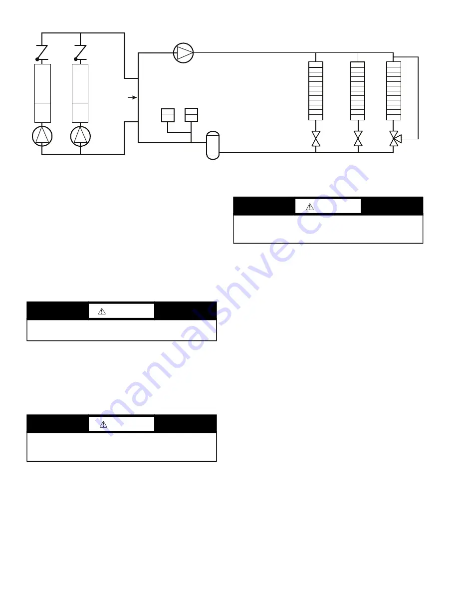
Fig. 16 —
Typical Air Separator and Expansion Tank Location on Primary-Secondary Systems
FIELD PIPING
When facing the coil header side of the unit, the inlet (return)
water connection is on the right. It is required that a field-sup
-
plied strainer with a minimum size of 20 mesh and blow-down
valve be installed within 10 ft (3.05 m) of the unit connection
to prevent debris from damaging coil tubes. The blow-down
valve allows removal of particulates caught in the strainer
without complete removal of the screen. The outlet (supply)
water connection is on the left.
The 09FC has water-side Victaulic-type connections. Provide
proper support for the piping. If security grilles have been added,
holes must be cut in the grilles for field piping and insulation, if
required.
Victaulic Coupling Installation
1. The outside surface of the pipe, between the groove and the
pipe end, must be smooth and free from indentations, projec
-
tions (including weld seams), and roll marks to ensure a leak-
tight seal. All oil, grease, loose paint, and dirt must be
removed.
2. Apply a thin coat of Victaulic lubricant or silicone lubricant to
the gasket sealing lips and exterior.
3. Position the gasket over the pipe end. Make sure the gasket
does not overhang the pipe end.
4. Align and bring the two pipe ends together. Slide the gasket
into position and center it between the groove in each pipe
end. Make sure no portion of the gasket extends into the
groove in either pipe end.
5. Install the housings over the gasket.
NOTE: Make sure the housings' keys engage the grooves
completely on both pipe ends.
6. Install the bolts, and thread a nut finger-tight onto each bolt.
For couplings supplied with stainless steel hardware, apply an
anti-seize compound to the bolt threads. Make sure the oval
neck of each bolt seats properly in the bolt hole.
7. Tighten the nuts evenly by alternating sides until metal-to-
metal contact occurs at the bolt pads. Make sure the housings'
keys engage the grooves completely.
NOTE: It is important to tighten the nuts evenly to prevent
gasket pinching.
8. Visually inspect the bolt pads at each joint to ensure metal-to-
metal contact is achieved.
See Fig. 18-22 for a typical piping diagram of a 09FC unit. Drain
connections are located at the bottom of the entering and leaving
water piping at the end of the unit. See Fig. 5-11 for connection lo
-
cation.
The EWT and LWT thermistors are field-installed. See Fig. 17.
The thermistors are supplied with the unit coiled up near the enter
-
ing and leaving water connections. Thermowells are included with
the unit and are placed in the control panel. Thermowells are
1
/
4
in.
NPT to be installed in entering and leaving piping. Allow 4 pipe
diameters or straight pipe upstream of thermistor mounting loca
-
tion to achieve mix flow for an accurate temperature measure
-
ment. See Fig. 18-21 for suggested locations. On larger units,
09FC050-080, the LWT thermowell must be placed in the com
-
mon piping if unit is piped in parallel arrangement.
In sound sensitive applications, consider the installation of piping
vibration isolators.
NOTE: Expansion tanks for 30XV/09FC hydronic kits must be installed for chillers piped in parallel in the primary water loop.
Zone 1
Zone 2
Zone 3
Distribution Pump
Air Separator
with Vent
Expansion
Tank(s)
Decoupler
Chiller 1
Chiller 2
09FC
09FC
WARNING
Safely relieve the pressure, and check for zero residual
pressure before removing the caps.
CAUTION
Always use a compatible lubricant to prevent the gasket from
pinching or tearing during installation. Failure to follow this
instruction could result in joint leakage.
CAUTION
Make sure the gasket does not become rolled or pinched while
installing the housings. Failure to follow this instruction could
cause damage to the gasket, resulting in joint leakage.
Summary of Contents for 09FC020
Page 8: ...8 Fig 5 09FC 020 Unit Dimensions...
Page 9: ...9 Fig 6 09FC 030 Unit Dimensions...
Page 10: ...10 Fig 7 09FC 040 Unit Dimensions...
Page 11: ...11 Fig 8 09FC 050 Unit Dimensions...
Page 12: ...12 Fig 9 09FC 060 Unit Dimensions...
Page 13: ...13 Fig 10 09FC 070 Unit Dimensions...
Page 14: ...14 Fig 11 09FC 080 Unit Dimensions...
Page 69: ......


