4-17
the refrigeration unit from the highly corrosive sea
atmosphere or if the protective paint system is scratched
or damaged, clean area to bare metal using a wire brush,
emery
paper or equivalent
cleaning method.
Immediately following cleaning, spray or brush on zinc
rich primer. After the primer has dried, spray or brush on
finish coat of paint to match original unit color.
4.22 POWER AUTOTRANSFORMER (OPTIONAL)
The transformer is either the whole-unit transformer
(item 1 or item 3, Figure 1-6) or the evaporator
transformer (item 2, Figure 1-6). Also, refer to Table 1-1
to determine which transformer is listed for the unit.
For the modular transformer (item 3, Figure 1-6):
If the unit does not start, check the following:
a. Make sure the 460 vac (yellow) power cable is
plugged into the receptacle (item 5, Figure 1-6) and
locked in place.
b. Make sure that circuit breakers CB-1 and CB-2 are
in the “ON” position. If the circuit breakers do not hold
in, check voltage supply.
c. There is no internal protector for this particular
transformer design, therfore, no checking of the internal
protector is required.
For transformer (item 1, Figure 1-6) or the evaporator
transformer (item 2, Figure 1-6):
If the unit does not start when connected to a 190/230
vac power supply, check the following:
a. Make sure circuit breaker (CB-2) is in the ON
position. If CB-2 does not hold in, check voltage supply.
b. Check to see if the transformer internal protector
(IP-AUTO-TRANS) is closed. Allow a reasonable length
of time for transformer to cool down. The transformer
includes two (2) internal protectors. Only one is wired
into the system as the second protector is a spare.
c.
To Check for Continuity Across the Internal Protector
(IP-AUTO-TRANS):
1. Turn power OFF and disconnect power source.
2. Disconnect white wires
1 and 2
from the KA and
KB connector on the Controller.
3. Check for continuity across the internal
protector (IP). If (IP) is open and will not reset, connect
wires
3 and 4
(18 gauge) to the KA and KB connector.
Check to see if unit will start.
d. If the internal protector and circuit breakers (CB-1
and CB-2) are good, check the transformer. Use a
voltmeter and with the primary supply circuit ON check
the primary (input) voltage (230 vac). Next, check the
secondary (output) voltage (460 vac) at the voltage
selector switch. The transformer is defective if voltage is
not available.
4.23 SENSOR CHECKOUT PROCEDURE
(AMBS, DTS, RRS, RTS, SRS & STS)
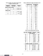
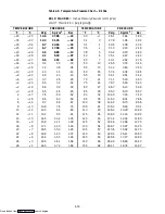
An accurate ohmmeter must be used to check the
resistance values shown in Table 4-1.
Due to the variations and inaccuracies in
ohmmeters, thermometers or other test equipment, a
reading within 2% of the chart value would indicate a
good sensor. If a sensor is defective, the resistance
reading will usually be much higher or lower than the
resistance values given in Table 4-1.
4.23.1 Checking Sensor (RRS, RTS, SRS or STS)
a. Place the sensor (sensing bulb) in 0
_
C (32
_
F)
ice-water bath. Ice-water bath is prepared by filling an
insulated container (of sufficient size to completely
immerse bulb) with ice cubes or chipped ice, then filling
voids between ice with water, and agitating until mixture
reaches 0
_
C (32
_
F) as shown by a laboratory
thermometer.
b. Start unit and check air temperature/data readout on
the control panel. You should have a reading of 0
_
C
(32
_
F); if not, continue on to the following step.
c. Turn unit OFF and disconnect power supply.
d. Refer to section 4.28 for removal of the Controller or
DataCORDER module.
RTS or STS:
In the box there is a plug connector marked (EC) that
is connected to the Controller module, find the wires
marked RTS or STS, depending on which sensor needs
replaced. Follow that wire to the connector and using the
pins of the plug, measure the ohms resistance. Readings
are shown in Table 4-1.
RRS or SRS:
In the box there is a plug connector marked (ED)
that is connected to the optional DataCORDER module,
find the wires marked RRS or SRS, depending on which
sensor needs replaced. Follow that wire to the connector
and using the pins of the plug, measure the ohms
resistance. Readings are shown in Table 4-1.
4.23.2 Replacing Sensor (RRS, RTS, SRS or STS)
a. Turn unit power OFF and disconnect power supply.
b. Cut cable 15.24 cm (6 inches) from shoulder of
defective sensor and discard.
c. Cut one wire of existing cable 25.4 mm (1.0 inch)
shorter than the other wire.
d. Cut one replacement sensor wire (opposite color)
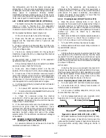
back 25.4 mm (1.0 inch). (See Figure 4-21.)
Sensor
Shoulder
25.4 mm (1.0 inch)
6.35 mm (1/4 inch)
Figure 4-21. Sensor (RRS, RTS, SRS or STS)
e. Strip back insulation on all wiring 6.35mm (1/4 inch).
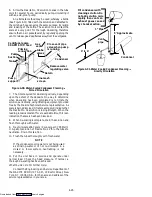
f. Slide a large piece of heat shrink tubing over the
cable and the two small pieces of heat shrink tubing over
the wires before adding crimp fittings as shown in
Figure 4-22.
Downloaded from

