1-33
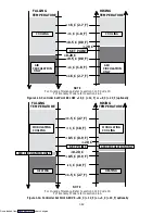
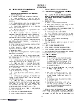
--- Bulb Mode Start
--- Bulb Mode End
1.14.2 DataCorder Programming (Memory) Cards
The programming cards are used for loading soft-
ware into the DataCorder. This is the same concept as
using a floppy diskette to load software into a personal
computer.
The software that can be loaded into the DataCorder
module, comes in one of two forms. Either “Operational
Software” or “Configuration Software.”
Operational Software:
This is the software that makes the DataCorder mod-
ule do what it does. Wake the unit up at a specified time,
request information from other modules in the unit, take
readings from probes, etc.
Configuration Software:
This is the software that tells the Operational Soft-
ware what physical components are built into the Con-
tainer Unit, how many sensors to record, what recording
interval should be used, etc..
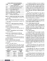
D
Configuration Type --- Standard or Generic
D
Sensor Logging (Network) --- Average or Snapshot
D
Sensor Logging (Thermistor) --- Average, Snap-
shot or USDA
D
Sensor Format --- 1 Byte or 2 Byte (i.e. Accuracy)
D
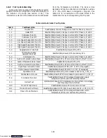
Sensor configuration --- 2, 5, 6, 9, 24, 54, 64 and 94
sensors, refer to section 1.14.3.h.
D
Logging Interval --- 15, 30, 60 or 120 Minutes
D
DataCorder alarm format --- Auto, on or off
Programming cards with either Operational Soft-
ware or Configuration Software are available thru CTD
Replacement Components Group.
The use of a programming card in the field, should
only occur under unusual circumstances. Some of these
circumstances may include:
a. A DataCorder module has an older version of
Operational Software, and the need exists to upgrade to a
newer version of the software.
b. A physical component in the container unit is
changed to something different, resulting in a different
Configuration for the Unit.
c. A DataCorder module was damaged in such a way
that the integrity or existence of software within the mod-
ule, is questionable.
Procedure for loading software:
Refer to section 4.28.2.
1.14.3 Functions
To access the DataCorder functions codes or alarms,
first press the ALT. MODE key, then press the applicable
key for functions (CODE SELECT) or alarms (ALARM
LIST).
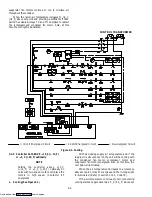
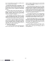
a. Memory Card Operations
The DataCorder will support the download of code
via a memory card using the software port. See
Figure 1-11.
b. Keypad/Display Interface
The DataCorder uses the controller module display
and keypad. The display formats and data are read from
the DataCorder as they are needed. Dynamic data is read
from the DataCorder once every second. Data to be
written to the DataCorder is sent once the editing session
is complete. The DataCorder contains three types of
display parameters. These are Configuration Codes,
Display Codes, and Alarm Codes.
c. DataCorder Power-Up
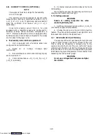
The DataCorder may be powered up in several ways:
1.
Normal AC power:
The DataCorder is powered
up when the unit is turned on via the stop-start switch
(ST).
2.
Normal DC power:
If a rechargeable battery pack
is installed (fully charged), the user may plug the
interrogation cable into the front interrogation
receptacle and the DataCorder will power up for
communications.
Or a 12 volt DC battery pack is plugged into the back
of the interrogation cable which is then plugged into the
rear interrogation port. (No rechargeable battery pack is
required with this method.) The user may now
interrogate the DataCorder, however, only the
DataCorder is powered up and not the Controller.
3.
Push button on the DataCorder when a battery
pack is used:
The user must depress the manual battery
switch (see Figure 1-11) for about ten seconds to power
up the DataCorder and to perform a test on the
rechargeable battery. If the battery is good, the “STAT
LED” will first illuminate followed shortly by the
“BATTERY STATUS LED”. Once the “BATTERY
STATUS LED” starts flashing, the user can assume the
battery charge is sufficient for normal battery back-up
operation at the time of the test. If, for some reason, the
“STAT LED” does not illuminate or the “BATTERY
STATUS LED” illuminates to a steady position (does not
flash) or does not illuminate at all, then the user can
presume that the battery is in need of a charge.
4.
Real Time Clock (RTC) because a logging interval
has expired:
If the DataCorder is equipped with a charged
battery pack and AC power is not present, the
DataCorder will power up when the RTC indicates that a
data recording should take place. When the DataCorder
is through recording, it will power down.
Downloaded from

