2-1
SECTION 2
OPERATION
2.1 PRE-TRIP INSPECTION (Before Starting)
WARNING
Beware of unannounced starting of the evaporator
and condenser fans.
a. If container is empty, check inside for the following:
1. Check channels or “T” bars on floor for
cleanliness. Channels must be free of debris for proper air
circulation.
2. Check container panels, insulation and door seals
for damage. Effect permanent or temporary repairs.
3. Visually check evaporator fan motor mounting
bolts for proper securement.
4. Check for dirt or grease on evaporator fan or fan
deck and clean if necessary.
5. Check evaporator coil for cleanliness or
obstructions. Wash with fresh water. (Refer to section 4.14)
6. Check defrost drain pans and drain lines for
obstructions and clear if necessary. Wash with fresh water.
7. Check panels on refrigeration unit for loose bolts
and condition of panels. Make sure T.I.R. devices are in
place on access panels.
b. Check condenser coil for cleanliness. Wash with fresh
water. (Refer to section 4.17)
c. Check position of fresh air makeup vent cover.
Operator must determine if fresh air makeup vent cover is
to be opened or closed.
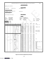
d. Open Partlow recording thermometer (if so equipped)
door and do the following:
1. Manually wind clock on recording thermometer
(key is located in a clip.) KEY MUST STAY WITH THE
THERMOMETER
2. Lift stylus (pen) by pulling the marking tip outward
until the stylus arm snaps into it’s retracted position.
3. Install new chart on recording thermometer
making sure chart is under the four corner tabs. Lower the
stylus until stylus has made contact with the chart. Then
close and secure door.
e. Open Saginomiya recording thermometer (if so
equipped) door and do the following:
1. Check Chart drive battery condition. (Refer to
section 4.20)
2. Lift stylus (pen) by pushing in the stylus lifter and
rotating the lifter clockwise (raising stylus at same time)
until lifter locks in position.
3. Install new chart on recording thermometer
making sure chart is under the four corner tabs. Release
stylus lifter by pushing down and rotating lifter
counterclockwise until stylus lifter locks in position and
stylus has made contact with chart. Then close door.
f.
Open control box door. Check for loose electrical
connections or hardware.
g. Check color of moisture-liquid indicator.
h. Check oil level in compressor sight glass.
i.
Start refrigeration unit. (Refer to section 2.3.)
2.2 STARTING AND STOPPING INSTRUCTIONS
CAUTION
Make sure that the unit circuit breaker(s) (CB-1
& CB-2) and the start-stop switch (ST) are in the
OFF position before connecting to any electrical
power source.
a. Starting the Unit
1. Refer to Pre-Trip Inspection, section 2.1.
2. Check power source for proper voltage. Connect
unit power plug and turn main power ON.
3. Turn refrigeration unit circuit breaker(s), and the
start-stop switch ON (position “1”).
4.
Units equipped with a DataCORDER:
Trip start is initiated by depressing the ALT. MODE
key and selecting Code dc30, then depressing the
ENTER
key for 5 (five) seconds.
5. Refer to section 2.3 after unit is running.
b. Stopping the Unit
Turn the start-stop switch to position “0” (OFF
position).
2.3 AFTER STARTING INSPECTION
a. Check rotation of condenser and evaporator fans.
b. Check compressor oil level. (Refer to section 4.10)
c. Run unit at least 5 minutes to stabilize. Start controller
Pre-Trip diagnostics. (Refer to section 1.13)
2.4 UNIT OPERATION
2.4.1 Crankcase Heater
Whenever the crankcase heater is installed,
it will be operational whenever the
compressor is off and their is power to the
unit. The heater is connected to a set of
normally closed auxillary contacts on the
compressor contactor.
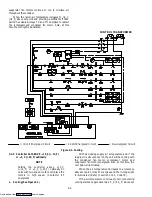
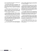
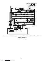
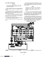
2.4.2 Cooling --- Controller Set BELOW ---10
_
C (+14
_
F)
or ---5
_
C (+23
_
F) optionally
NOTES
1. The suction solenoid valve (SSV) will be open
to increase the refrigerant flow rate and
cooling capacity unless SSV override is
activated.
2. In the frozen range the suction modulation
valve is 100% open.
3. Setting the controller below ---10
_
C (+14
_
F)
or ---5
_
C (+23
_
F) optionally on units with
two-speed motors will place the motors in low
speed (contactor ES energized).
When the return air temperature decreases to 0.2
_
C
(0.4
_
F) below set point, relays TC and TN de-energizes.
This results in de-energizing the compressor and condenser
fan motor. Also, the cool light is de-energized. The
Downloaded from

