background image


54

 
9-4 Printer diagram


This analyzer's inner printer is thermal printing method-applying printer.   


Replacement of printing paper

.   

 
9-4-1. Open the cover of the printer as shown on drawing 1. 

When opening the cover of the printer, grab the handle and pull it forward as shown on drawing. 
Then the cover opens.   


When replacing the printing paper, make sure the correct side, as the printing paper has   
pintable side. 


9-4-2.  Insert  the  paper  as  shown  on  drawing  2.  If  it  inserted  oppositely  with  wrong  side  of  paper,  it 

won't be printed, since only one side is printable. 

 
9-4-3. When the rubber stick of printer falls off or when replacing the rubber stick, place it with correct 

direction to fit to the gear.   


CAUTION : When rubber stick and printer parts is moistened or blemished, major parts of the 

printer could be damaged. When moistened, dry it before use.  
When blemished, clean it before use.


Summary of Contents for NGA6000

Page 1: ...4 This product should not be washed polished by volatile or toxic chemical materials like thinner 5 Please don t use the printer until the printing paper is prepared 6 If the equipment is wiped with a...

Page 2: ...ng 5 Chapter 3 Introduction of NGA 6000 3 1 Specification 6 3 2 Appearance 7 3 3 Front view and description 8 3 4 Rear view and description 10 3 5 Basic accessory 12 Chapter 4 Circuits of NGA 6000 4 1...

Page 3: ...rsion indication 40 7 8 Time setup 41 7 9 NOx setup 42 7 10 Standard gas calibration 43 Chapter 8 Fault diagnosis and troubleshooting 51 Chapter 9 Various Expendables Maintenance 9 1 Case segregation...

Page 4: ...aim procedure for example absence of type or serial number 1 2 Guarantee claim procedure Warning This product is not designed for outdoor installation so that a damage or fault originated from the out...

Page 5: ...rough and properly understood for correct usage This analyzer should be manipulated only by the trained personnel who well understood the usage A spot check or periodical check should be executed in a...

Page 6: ...asuring range Lambda 0 2 000 AFR 0 0 99 0 Resolution 0 001 0 1 Display 4 digit 7segment LED 4 digit 7segment LED Measuring range NOx Option 0 5000 ppm Resolution 1 ppm Display 4 digit 7segment LED Rep...

Page 7: ...motorcycle which emits high density of HC Measuring range of the HC is 0 20 000 ppm and display window is specially custom made in order to indicate 5 digits segments and for CO CO2 O2 the display wi...

Page 8: ...proceeding status 3 3 3 CO2 display window This displays the CO2 density and program proceeding status 3 3 4 O2 display window This displays the O2 density and program proceeding status 3 3 5 Lambda d...

Page 9: ...e of correcting the datum point or moving a figure or digit 3 3 10 KEY PURGE Used in time of doing a purge or executing a value increase 3 3 11 ENTER KEY Used in time of measuring or approving a suppl...

Page 10: ...f measuring the emitted gas 4GAS Analyzer and water to correct the gas is outcome 3 4 4 MAIN FILTER This condenses the vapor contained in the automobile emitting gas so that it prevents other material...

Page 11: ...is is a terminal to be directly connected with a normal PC printer 3 4 9 RS232 PORT This is a communication terminal through which a PC can operate the program 3 4 10 POWER SWITCH A power on off termi...

Page 12: ...12 3 5 Basic accessory 3 5 1 Basic accessory...

Page 13: ...4 M071 1 COPY 5 MAIN FILTER QG0 A017 10PC 6 DUST FILTER QG0 A013 5PC 7 ZERO FILTER QG0 A014 2PC 8 PROBE FILTER QG0 A021 10PC 10 FUSE 250V 2A QG0 E022 2PC 11 POWER CABLE QG0 E019 1PC 14 INNER PRINTER Q...

Page 14: ...analyzing method a flashing ramp which flashes the infrared rays is attached at the one end of the sample cell and at the other end a detecting sensor is attached so that it can detect the component o...

Page 15: ...15 4 2 Guiding diagram 4 3 Electrical circuit diagram...

Page 16: ...he fitting condition is not good and the air comes into flow from outside it may yield an incorrect measured value Therefore please carefully verify the fitting condition before use 5 1 2 Turn off the...

Page 17: ...f measuring probe filter and various filters located in the rear of the analyzer 5 1 4 Verify again the connection status of the analyzer and then turn on the power switch 5 1 5 Connect the ground cab...

Page 18: ...be may be so hot during the operation so that it should be carefully handled not to be burned in insertion or removal It needs to be noted that you should not stay in the gas emitting place during the...

Page 19: ...ON NGA 6000 will perform the initialization process for 10 seconds displaying the following CO HC ppm CO2 O2 Lambda AFR NOX NGA 6000 will display current set date and time for about five seconds CO H...

Page 20: ...diagnosis in the order of display window verification communication internal sensor and memory as follows If the items diagnosed are normal NGA 6000 will display the PASS message Self diagnosis execu...

Page 21: ...21 CO HC ppm CO2 O2 Lambda AFR NOX CO HC ppm CO2 O2 Lambda AFR NOX CO HC ppm CO2 O2 Lambda AFR NOX...

Page 22: ...of equipment use Activate the pump one minute before ending the warming up and clear up the inside of equipment with the clean air CO HC ppm CO2 O2 Lambda AFR NOX The initial calibration is automatica...

Page 23: ...e window showing that NGA 6000 is in a ready for measurement CO HC ppm CO2 O2 Lambda AFR NOX Power ON Initialization Process 10 seconds Self Diagnosis Warming up between 2 and 8 minutes STAND BY Measu...

Page 24: ...OFF ESC ENTER ZERO PURGE PRINT MENU Press the ESC key after the measurement or the purge function And the suction pump will be deactivated CO HC ppm CO2 O2 Lambda AFR NOX If the window displays as sh...

Page 25: ...will elongate life cycle of a filter exchange period and in long term will elongate the life cycle of pump and other parts as well Note It is recommended against the measurement of the exhaust gas in...

Page 26: ...120 seconds and internal sample cell for 20 seconds ESC ENTER ZERO PURGE PRINT MENU Press PURGE key and the following will be displayed The probe is cleaned for two minutes Place the employing end of...

Page 27: ...haust gas of a vehicle for a long time there may be lots of remaining gas in the probe and sample cell If the HC value indicates over 10 ppm after the zero calibration use this function CO HC ppm CO2...

Page 28: ...ill be decreased by 1 from 20 as shown in the figure below during the 20 seconds process of the zero calibration CO HC ppm CO2 O2 Lambda AFR NOX Note Build up a habit to clean NGA 6000 with the PURGE...

Page 29: ...lean the inside of NGA 6000 with a clean air for about 2 3 minutes And then perform the zero calibration again Note 2 Activated Charcoal Filter It is also known as ZERO filter It either neutralizes or...

Page 30: ...tivation of the power saving mode Press ENTER key again to measure the exhaust gas for more than 10 minutes Pull the probe out of the exhaust outlet of the vehicle Then clean the inside of NGA 6000 wi...

Page 31: ...on to print out the measurement result of the exhaust gas Analyzer s inner printer is thermal printer Turn the printer on and be ready to print Press PRINT key when measuring value is stabilized PRINT...

Page 32: ...justing the desired figure press the key and the figure in the next digit blinks After registering the car number by using the and keys press the PRINT key Then the print starts Automotive Emission An...

Page 33: ...Press the MENU key NGA 6000 will operate according to the contents ESC ENT printed on the upper side of each key Use this key to change the setup positions HOLD When you stops measurement value tempor...

Page 34: ...ndow as shown above mount the leak test cap on the front side of the probe Press ENTER key The pump operates and the count values decrease by 1 from 20 during the 20 second leak test CO HC ppm CO2 O2...

Page 35: ...andby mode automatically unless other keys are pressed within 30 seconds after the leak test When the result is indicated as FAIL Check if the leak test cap is normally mounted Check the probe and hos...

Page 36: ...Press Select key twice in standby mode CO HC ppm CO2 O2 Lambda AFR NOX Press ENT key Perform the zero calibration for 20 seconds as shown below CO HC ppm CO2 O2 Lambda AFR NOX As the pump starts oper...

Page 37: ...ve another try from above If the result of the second try is over 20ppm FAIL sign is displayed Clean inside this analyzer by pressing the PURGE key when Fail is indicatedbecause remaining gas leaves f...

Page 38: ...O2 Lambda AFR NOX Selected fuel is indicated as in the above Use keys until it indicates the fuel to select Press ENTER key to setup the selected fuel For Example If the LPG fuel is selected the wind...

Page 39: ...ess MENU key four times from standby mode CO HC ppm CO2 O2 Lambda AFR NOX The value of Hcv and Ocv is not possible to change If it requires to change the value of Hcv and Ocv due to the difference of...

Page 40: ...random Multiple the propane density by the PEF values to convert into the N Hexane density Press MENU key for five times Then the PEF values are indicated as the following CO HC ppm CO2 O2 Lambda AFR...

Page 41: ...are increased or moved with the and keys Upon completing the setup press the ENTER key to store it The range of setup value is shown in the Table below Setup Contents Year Increase or decrease between...

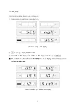
Page 42: ...mbda AFR NOX When it is set up to NOX display key changes display to YES or to NO Select YES for NOX display mode NO for non NOX display mode then press ENTER A is attached as shown below in the AFR A...

Page 43: ...libration 7 10 1 Precautions for the standard gas calibration The gas used for the standard gas contains poisonous compositions and causes a fatal damage to human body Perform the calibration process...

Page 44: ...nd the pressure gauge indicating both the first pressure and the secondary pressure 7 10 3 Connection method 7 10 3 1 Connection method by Standard gas Cylinder Connect the standard gas cylinder to th...

Page 45: ...control adjuster clockwise little by little to adjust the secondary pressure to 0 5 1 0 Kgf Open the flow control valve little by little to control the flow to 4 5 min Control the flow by using the p...

Page 46: ...NGA 6000 from being wrongly controlled due to poor manipulation of unskilled person However since the standard gas calibration severely affects the accuracy of analyzer the operator must fully underst...

Page 47: ...ess MENU key nine times ESC ENTER ZERO PURGE PRINT MENU The following message is indicated NGA 6000 operates according to the ESC ENTER printed on the upper part of each key CO HC ppm CO2 O2 Lambda AF...

Page 48: ...er the setup of the required number press key to move the blinking part to the next field Use keys to setup to standard gas value of gas cylinder then press ENTER key The each value of CO CO2 and O2 i...

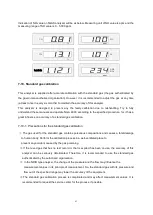
Page 49: ...stant pressure If the measurement values are in a stable state press both the ENTER key and MENU key at the same time to start the gas calibration CO HC ppm CO2 O2 Lambda AFR NOX If the gas calibratio...

Page 50: ...calibration and will return to the standby mode CO HC ppm CO2 O2 Lambda AFR NOX It is succeeded in HC and CO2 calibration but failed in CO O2 calibration If the FAIL is displayed return to the standb...

Page 51: ...Is any of probe hose or filter blocked Verify the probes hoses and filters Mem ERR Memory error Is the input power source well purified Turn off the power and reboot Zero ERR Zero Calibration error Is...

Page 52: ...r turning the power off only if there is a necessity to turn the power on turn it on 9 1 Case separation diagram 9 1 1 Loosen five screws four in the side and one in the rear by using the screwdriver...

Page 53: ...is as follows Loosen B counterclockwise for separation Then replace the probe filter with new one and assemble it again in the reverse order of disassembly 9 3 Main filter 9 3 1 Loosen the main filte...

Page 54: ...make sure the correct side as the printing paper has pintable side 9 4 2 Insert the paper as shown on drawing 2 If it inserted oppositely with wrong side of paper it won t be printed since only one s...

Page 55: ...y it is set at 100 9 5 3 To set the density too high it could shorten the printer s life span So mind to set not too high CAUTION 1 Set Mode is generally used in winter time or very cold area since in...

Page 56: ...d replace the O2 sensor 9 6 2 Turn the analyzer power off 9 6 3 Split upper case of analyzer and dismount the O2 sensor connector 9 6 4 Turn the O2 sensor counterclockwise for splitting 9 6 5 After ve...

Page 57: ...split C and D 9 7 3 After replacing the filter with new one re assemble it in the reverse order of disassembly 9 8 Zero filter Activated charcoal filter 9 8 1 It is recommended to replace the zero fil...

Page 58: ...wer is not turned on because the fuse is gone replace it 9 9 2 Turn the analyzer power off 9 9 3 Insert the screwdriver or pin to A part for dismounting 9 9 4 After replacing the fuse 250V 2A re assem...

Page 59: ...t panel case QG0 M066 420 170 30 Rear panel case QG0 M067 417 167 20 Upper cover case QG0 M064 420 140 270 Main filter supporter QG0 M068 40 20 34 Main filter L type nipple QG0 M016 21 10 19 Main filt...

Page 60: ...ification W D H mm Solid diagram Remarks Activated charcoal filter Zero filter QG0 A014 35 81 Probe filter QG0 A021 23 82 Check valve QG0 A006 19 43 Orifice QG0 A007 5 6 Printer QG4 M023 Printer case...

Page 61: ...ification W D H mm Solid diagram Remarks Probe handle QG0 A022 39 119 Probe tip QG0 M026 8 345 Probe stainless steel QG0 M027 Probe spring QG0 M028 Probe hose QG0 A015 6 5 7000 Solenoid supporter QG0...

Page 62: ...pecification W D H mm Solid diagram Remarks Fuse QG0 E022 250V 2A Power cable QG0 E019 0 75SQMM 3C RS232 port QG0 E002 53 12 15 Fan QG0 E009 80 25 80 Pump QG0 A001 80 70 128 O2 sensor QG4 E015 29 41 N...

Page 63: ...roduct number Specification W D H mm Solid diagram Remarks Display PCB QG4 N019 152 18 123 T type fitting QG4 M006 5 31 21 Operation manual QG4 M071 OPERATION MANUAL Case handle QG0 M150 Leak test cap...

Page 64: ...nd O2 K1 Enter constant 6 or 8 for vapor in combustion stroke K1 is the constant that converts the value measured by Non Dispersed InfraRed NDIR into the value measured by Flame Ignite Detect FID and...

Reviews: