


© 2002 Carlo Gavazzi Industri A/S. All rights reserved
9
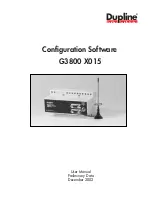
G 3800 X015 Configuration Software
October 2002
When the basic settings have been made under “Basic Setup”, the functions of the remaining channels to be
used are defined as follows:
Activate one of the channels, then click on the right mouse button for pop-up menu. Click on the desired
channel function with the left mouse button. The channel is thereby assigned a symbol indicating the selected
channel function. Click on the symbol with the left mouse button, and the parameters which can be set for
that particular channel function can be viewed in the properties window.
The arrow keys can also be used to select channel function in the pop-up menu. Furthermore, channel func-
tion can be selected by clicking on different letters. To see how to select functions by clicking on letters,
select the General information menu under Help.
Tool tip
When the cursor is positioned on a channel button, a bar appears indicating channel number, describing
channel type and showing the user-defined channel description.
1.2.6. Configuration of channel functions