


50
© Carlo Gavazzi A/S
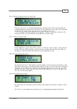
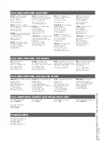
Programming the CPM Module
By means of the programming tool GP7380 0080 the installer can program the CPM module GP3482
9091 724�
Fig. 49
The CPM modules do not require power during programming� The power is supplied from the pro-
grammer GP7380 0080 in program mode�
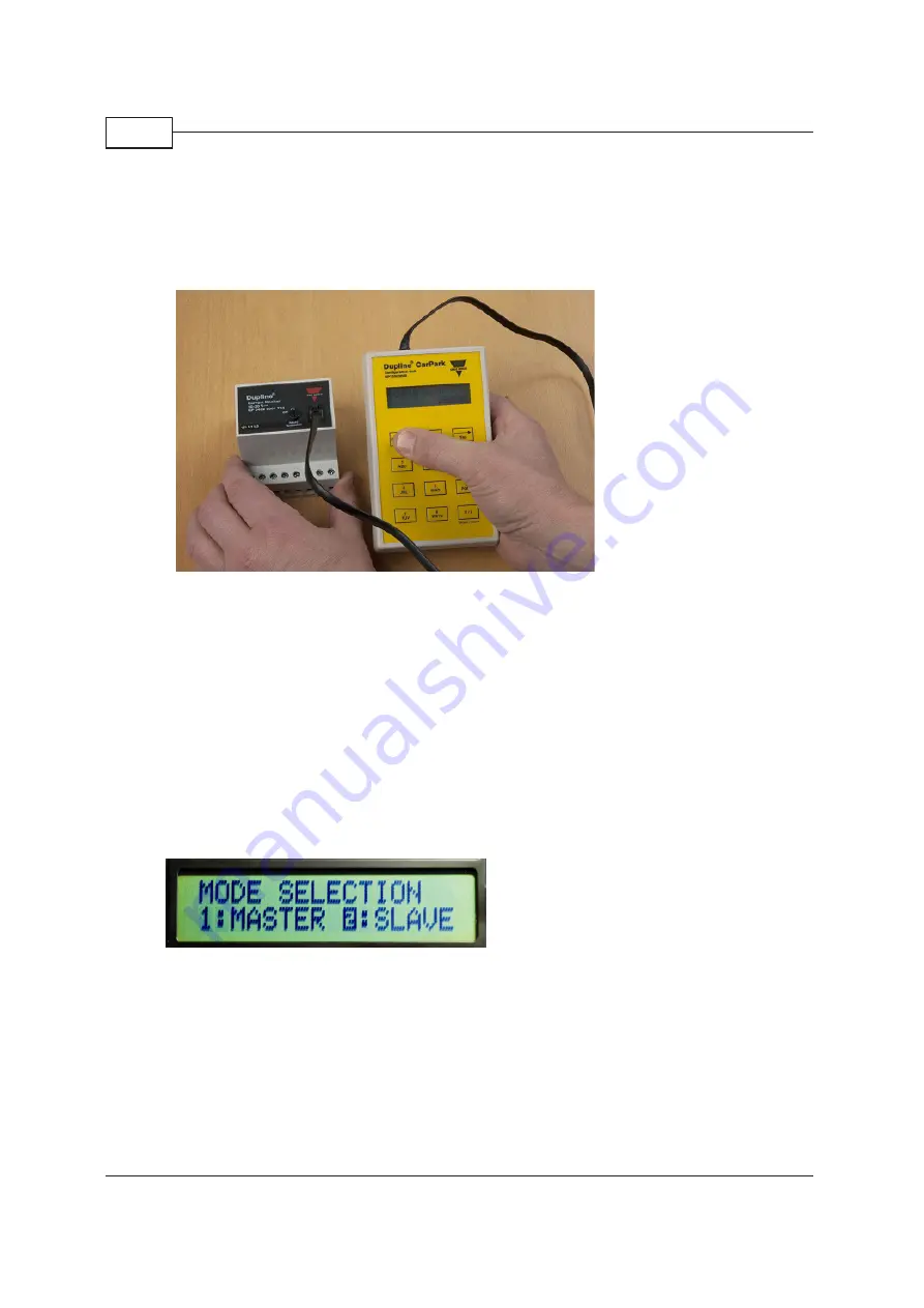
The CPM module can be programmed to:
•
slave mode (used with sensors on the L1 bus)
•
master indicator mode (used to collect data from the selected segments on the L1 bus to
the L2 bus)
•
master mode (Same as master indicator mode yet transmits also the multiplex signal to the
entire Parking Guidance System network)
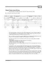
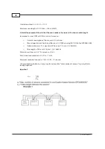
Fig. 50: Configuration of master/slave
Slave Mode
A slave CPM is connected directly to the sensors� Each slave CPM can handle up to 120 sensors� The
segment to which the sensors are connected is named the L1 bus� The communication between the
slave CPMs to the master CPM is named the L2 bus�
The maximum ID number is 480� See Fig� 20� It means that it is possible to install 480 L1 segments in
a system�