3. Prepare Burner
(continued)
• The nozzle line heater needs power when the burner is in standby (no
call for heat from the appliance). Make sure the nozzle line heater is
powered directly from the 120 VAC HOT line, not through the appliance
operating control circuit. The nozzle line heater wiring should be shown
on the wiring diagram supplied with the appliance/burner unit.
• The nozzle line heater is supplied with an electrical disconnect harness,
allowing removal of the combustion head assembly without discon-
necting wires. Position the heater harness disconnect in the rear of
the blower housing, above the blower access cover. The wire leads to
the disconnect route through the side of the housing into the junction
box.
When first starting the burner, or after the service switch has
been off for some time, the heater requires about 15 minutes
to bring the oil to operating temperature.
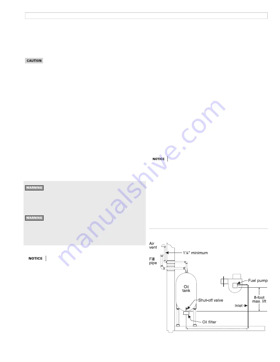
Figure 8 One-line fuel system
One-line fuel system requirements
See Figure 8. The standard burner fuel pump is a single-stage, 3450-RPM
oil pump. Apply this fuel pump only on one-line systems where the fuel
supply is on the same level with, or higher than, the burner. This ensures oil
flow by gravity. Also make sure the total lift does not exceed 8 feet (height
difference from bottom of oil tank to fuel pump). For other conditions, you
must provide a two-line fuel system. You may also have to change the fuel
pump to a two-stage type.
Inspect/install fuel supply
Inspect the oil supply system. Ensure that the fuel lines are
correctly sized and installed and that the fuel flow is unob-
structed, the oil tank is clean and only # 1 or # 2 heating oil
are supplied. Failure to supply a reliable oil flow could result
in loss of heat and potential severe equipment damage.
Nozzle line heater (optional)
• Oil burners often operate in spaces where temperatures tend to be
cool, typically 60°F or lower. Cool oil has higher viscosity, which can
affect atomization, ignition, combustion and fuel consumption. The
nozzle line heater avoids this problem by heating the nozzle line oil to
between 120°F and 130°F, resulting in smoother ignition and improved
combustion.
General guidelines:
• When installing oil lines, use continuous runs of heavy-wall copper
tubing if possible.
• Check fuel pump data sheet for recommended line sizing, lift limitations
and maximum length.
• Check all connections and joints to ensure they are air-tight.
• Use flare fittings. Do NOT use compression fittings.
• Never use pipe sealing tape. Fragments can break off and plug fuel line
components.
• Install a shut-off valve at the tank and one near the burner. (Use fusible
handle design valves when possible or when required by codes.)
• Install a large capacity fuel filter (rated for 50 microns or less) near the
burner.
Fuel pump bypass plug
The fuel pump is shipped with its bypass plug not installed,
intended for a one-line oil system. Install the bypass plug
only if connecting to a two-line oil system. Operating with
the plug in place on a one-line system will damage the fuel
pump and could lead to oil leakage and fire hazard.
If the fuel line or fuel supply is above burner, never exceed
3 PSIG pressure at the fuel pump inlet. Install a suitable OSV
to reduce the pressure. Operating the fuel pump with higher
inlet pressure could result in fuel pump seal damage, oil
leakage and potential fire hazard.
The National Oilheat Research Alliance (NORA) recommends
single pipe oil systems and high-quality filtration for all fuel
types. This should include at least a 10 micron Spin-on filter.
Double filtration provides even greater assurance clean fuel
will get to the pump. Contaminants in the tank that enter the
fuel supply to the burner can cause pump sticking/seizing.
These contaminants may increase in the early stages of tran-
sitioning to modern fuels (Ultra Low Sulfur and Bio Blends).
High quality filtration adds protection against pump sticking
MN66-3P 090721
– 9 –
Carlin Select EZ-66 Oil/Bio Fuel Burner Instruction Manual


