


14
ENG
pC0300020EN rel. 1.2 - 07.11.2013
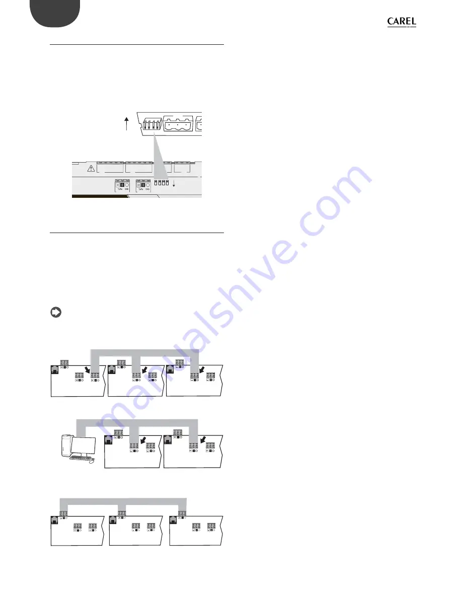
3.2 Port J26 confi guration
Compared to the pCO5, pCO5+ controllers are provided with 4
microswitches for confi guring serial port J26 (fi gure):
•
microswitches all down: port J26 set with Fieldbus hardware;
•
microswitches all up: port J26 set with BMS hardware*.
Factory confi guration: Fieldbus port.
(*) At the software level, in the 1Tool programming environment the serial
port is still the Fieldbus2.
C1
NO1
NO2
NO3
C1
C4
NO4
NO5
NO6
C4
C7
NO7
C7
NO8
C8
NC8
FieldBus
4
3
2
1
BMS
1 2
3 4
BMS
FieldBus
J26
J26
Fig. 3.b
3.3 Controller network connections
The pCO5+ comes with three kinds of serial ports: pLAN, Fieldbus, BMS.
The RS485 Fieldbus serial port is designed with Master-type hardware,
while the RS485 BMS serial port has Slave-type hardware. The protocols
used on the RS485 Fieldbus port are, due to the nature of the port, Master
protocols (CAREL Master or Modbus RTU Master), although in special
cases Slave protocols can be used (CAREL Slave or Modbus RTU Slave),
adopting the necessary measures. Likewise, Slave protocols are applied
on the RS485 BMS port, although under certain conditions Master
protocols can also be used.
Note:
The pLAN network is multi-master, meaning that each
controller can work as Master or Slave at the same time.
J25 BMS2 J26 FBus2
J11 pLAN
pCO5+
MASTER
J25 BMS2 J26 FBus2
J11 pLAN
pCO5+
J25 BMS2 J26 FBus2
J11 pLAN
pCO5+
MASTER - SLAVE network
SLAVE
SLAVE
Fig. 3.c
PC
MASTER
J25 BMS2 J26 FBus2
J11 pLAN
pCO5+
J25 BMS2 J26 FBus2
J11 pLAN
pCO5+
SLAVE
SLAVE
Fig. 3.d
pLAN network
J25 BMS2 J26 FBus2
J11 pLAN
pCO5+
J25 BMS2 J26 FBus2
J11 pLAN
pCO5+
J25 BMS2 J26 FBus2
J11 pLAN
pCO5+
MASTER/SLAVE
MASTER/SLAVE
MASTER/SLAVE
Fig. 3.e
Important warnings:
•
By applying the appropriate impedance, a serial port with Master
(FBus) hardware supplies the network with the bias voltage required to
run all the connected devices, i.e. the master itself and its slaves.
•
Conversely, serial ports with slave hardware (BMS) do not provide bias
voltage, so it is always advisable to connect at least one device with
master hardware (FBus) to the network so that it is correctly biased.
•
However, no more than two devices with master hardware (FBus) can
be connected to the same network, otherwise the network’s total
bias impedance becomes too small and incapable of supplying the
required voltage to the RS485 network.
•
We recommend connecting the serial probes or other fi eld devices to
an optically-isolated version of the Fieldbus serial port or to serial port
TWO – Fieldbus 1 to exploit the fi ltering properties of optical isolation.
Special cases
•
In networks consisting only of slave HW devices, no more than 207
devices can be connected. The max. length allowed for the network
is 100 m.
DO NOT connect the 120Ω, 1/4W terminating resistors to the fi rst
and last devices;
•
In networks consisting only of Master HW devices, no more than 2
devices can be connected. The max. length allowed for the network
is 1000 m. If the network is longer than 100 m, apply the 120Ω, 1/4W
terminating resistors to the fi rst and last devices in the network;
•
connect the computer to a network with no more than 1 master HW
device or no more than 207 slave HW devices.
Summary of Contents for pCO5+
Page 2: ......
Page 4: ...4 ENG pCO5plus 0300020EN rel 1 2 07 11 2013...
Page 6: ...6 ENG pCO5plus 0300020EN rel 1 2 07 11 2013...
Page 43: ...43 ENG pCO5plus 0300020EN rel 1 2 07 11 2013...
Page 59: ......


