µRack
Cod. CAREL +03P220431 rel. 0.0 del 08/09/05 - preliminary version
19
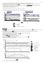
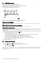
If between the start of two prevent cycles a time less than Prevent time 2 (parameter A14) elapses, the “Excessive prevent frequency” alarm is generated, A29.
The “Excessive prevent frequency” alarm (display only) is reset automatically, if, within Prevent time 3 (parameter A15), the prevent function is not activated again.
This alarm can be reset manually by the user, momentarily disabling the PREVENT function, using parameter /32.
Fig 7.1
Key:
OutPress
Discharge pressure
T
Time
NCmp
Number of suction steps required
ALPrv
High pressure prevention alarm
STPpr
Prevent HP activation threshold
T1
Time between compressor stops with prevent HP active
Dprev1
Step activation delay after end prevent HP (prevent time 1)
Dprev2
Minimum time for activation of high prevent frequency alarm (prevent time 2)
7.
Alarm management
The activation of an alarm, from digital input, causes the direct action on the devices involved, at the same time activating: the LED and a signal on the display. If
the compressors are called, the activation of an alarm on one compressor sends the call to another compressor.
The alarm information appears is displayed alternating with the value read by the control probe. If more than one alarm is active, the information appears on the
display in sequence. If the alarm situation is resolved, the relay is reset and the alarm message is cancelled. In the case of alarms with manual reset, the Reset
Alarms parameter (A19) needs to be accessed.
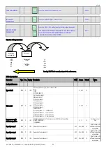
The alarm from digital input is typically detected when the contact “opens”, however the logic can be selected using the “digital input logic” parameter, /14.
7.1.
Alarms with automatic reset
When one or more automatic reset alarms are detected, these are signalled by:
•
Red
ALARM
LED on;
•
Alarm relay changes, if enabled.
Press the PRG/MUTE button.
If the cause of the alarms is resolved, the devices that have shutdown will restart normal operation, and the status of the signal devices changes as follows:
•
The alarm relay changes to normal status;
•
Red
ALARM
LED goes off..
If, in this situation, new alarms are activated, the initial situation will return.
The signal will remain active until the operator manually sets the reset alarms parameter A19.
7.2.
Alarms with manual reset
The compressor thermal overload (parameter /29) fan thermal overload (parameter /30) alarms can be set as manual reset.
When one or more manual reset alarms are detected, these are signalled by:
•
Red
ALARM
LED on;
•
Alarm relay changes, if enabled.
If the cause of the alarms has been resolved, the red LED stays on to inform the user that alarms have been activated during the day. In this situation, the alarm
relay remains in an alarm condition and the devices remain disabled until the user deleted the alarm messages using parameter A19.
If, in this situation, new alarms are activated, the initial situation will return..
If the causes no longer exist, the status of the signal devices changes as follows:
•
The alarm relay changes to normal status;
•
Red
ALARM
LED goes off..
NCmp
OutPress
STPpr
T[s]
T[s]
1
2
3
4
Dprev1
T1
Dprev2
ALPrv
T[s]
Summary of Contents for mRack
Page 1: ...µRack Standard compressor racks single two circuit ...
Page 2: ......
Page 4: ......
Page 37: ...µRack Cod CAREL 03P220431 rel 0 0 del 08 09 05 preliminary version 33 ...
Page 39: ......


