µRack
Cod. CAREL +03P220431 rel. 0.0 del 08/09/05 - preliminary version
29
13.
Programming key (code PSOPZKEYA0)
The programming keys PSOPZKEY00 and PSOPZKEYA0 for Carel controllers are used to copy the complete set of parameters to the µRack.
The keys must be connected to the connector (4 pin AMP) on the controllers, and can operate when the instruments are either on or off, according to the
instructions for the specific controller.
There are two main functions, which are selected using the two dipswitches (located under the battery cover). These are:
• Load the parameters from a controller to the key (UPLOAD);
• Copy from the key to one or more controllers (DOWNLOAD).
Warning: The parameters can only be copied only between instruments with the same product code. The upload operation, on the other hand, is always possible.
To assist the identification of the key to be used, CAREL has applied a label that can used to describe the programming made or the unit that the data refers to.
IMPORTANT NOTE: The key can only be used on µRack controllers that have the same firmware version.
Refer to the programming key instruction sheet for further details.
14.
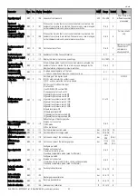
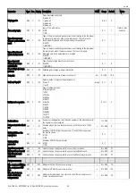
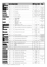
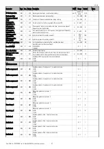
Supervisor management
The controller can be connected to a local or remote supervisor/telemaintenance system for managing the unit.
The variables sent and received by the supervisor are shown in the tables below, with reference to the following key:
R Read
Send from the µRack to the supervisor. Not modifiable
R/W Read-
Write
Received and sent from the µRack to the supervisor. Can be modified by the supervisor.
Analogue variables
Flow
Index
Description
R 1
Probe
B4
R 2
Probe
B1
R
3
Probe B2 (ambient air)
R
4
Probe B3 (outside air )
R/W
5
Suction set point circuit 1 “r01”
R/W
6
Differential circuit 1 “r02”
R/W
7
Suction set point circuit 2 “r03”
R/W
8
Differential circuit 2 “r04”
R/W
9
Min suction set point 1 “r12”
R/W
10
Max suction set point 1 “r13”
R/W
11
Min suction set point 2 “r14”
R/W
12
Max suction set point 2 “r15”
R/W
13
Fan set point “r16” (bar)
R/W
14
Fan set point “r16” (°C)
R/W
15
Fan differential “r17”(bar)
R/W 16 Fan
differential
“r17”(°C)
R/W
17
Min fan set point “r25”(bar)
R/W
18
Min fan set point “r25” (°C)
R/W
19
Max fan set point “r26”(bar)
R/W
20
Max fan set point “r26”(°C)
R/W
21
Fan inverter set point “r18” (bar)
R/W
22
Fan inverter set point “r18” (°C)
R/W
23
Fan inverter differential “r19” (bar)
R/W
24
Fan inverter differential “r19” (°C)
R/W
25
HP suction 1 alarm threshold “A01”
R/W
26
LP suction 1 alarm threshold “A03”
R/W
27
HP suction 2 alarm threshold “A05”
R/W
28
LP suction 2 alarm threshold “A07”
R/W
29
HP discharge alarm threshold “A09”
R/W
30
HP discharge alarm threshold “A09” (°C)
R/W
31
LP discharge alarm threshold “A10” (bar)
Summary of Contents for mRack
Page 1: ...µRack Standard compressor racks single two circuit ...
Page 2: ......
Page 4: ......
Page 37: ...µRack Cod CAREL 03P220431 rel 0 0 del 08 09 05 preliminary version 33 ...
Page 39: ......

