


28
ENG
c.pCO sis
tem
a
+
0300057EN
re
l. 1.2 - 29.05.2017
5. INPUT/OUTPUT CONNECTIONS
5.1 Power
supply
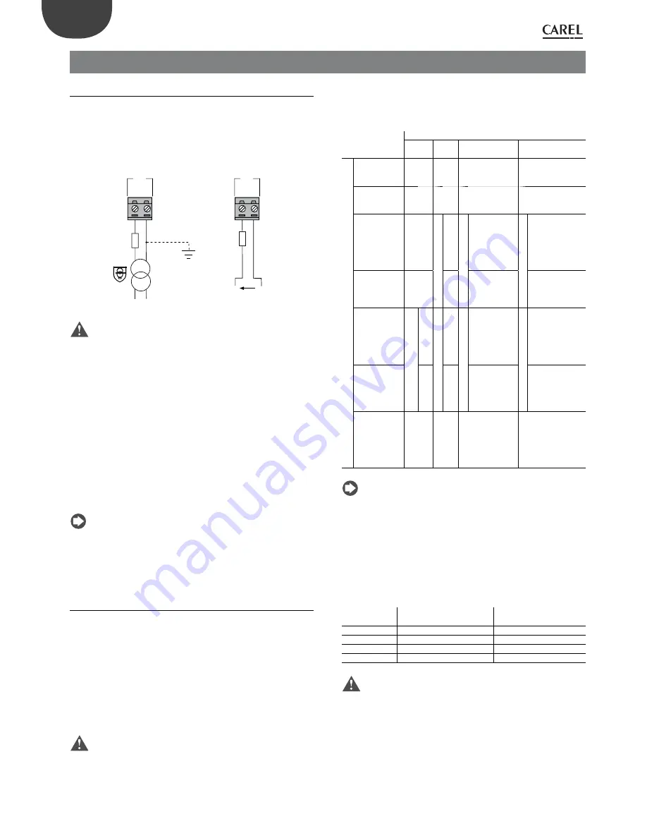
The figure below shows the power supply connection diagram. Use
a class II safety isolation transformer with short-circuit and overload
protection. See the Technical Specifications table for information on the
size of the transformer required by each model (see chap. 13)
.
2
4
Vac
230
Vac
2.5
A
T
G
G
0
J1
28...3
6
Vdc
2.5
A
T
G
G
0
J1
-
+
AC
DC
Fig. 5.a
Important:
•
power the c.pCO built-in driver with AC voltage only, with the
transformer secondary winding earthed;
•
if the Ethernet connection is featured and used, the transformer
secondary must be earthed;
•
using a supply voltage other than specified can seriously damage the
controller;
•
if the transformer secondary is earthed, make sure that the earth
conductor is connected to terminal G0. This applies to all the devices
connected to the c.pCO through a serial network;
•
if more than one c.pCO board is connected to a pLAN network, make
sure that the G and G0 references are observed (G0 must be maintained
for all controllers);
•
the power supply to the controller(s) and the terminal(s) should be
kept separate from the power supply to the other electrical devices
(contactors and other electromechanical components) inside the
electrical panel.
Note:
•
when the controller is powered, the yellow LED lights up;
•
refer to the diagrams in par. 4.4 in case of controllers connected to a
pLAN network and installed in the same electrical panel or in separate
panels.
5.2 Universal
inputs/outputs
Universal inputs/outputs are distinguished by the letter U...
They can be configured from the application program for many different
uses, such as the following:
•
passive temperature probes: NTC, PTC, PT100, PT500, PT1000;
•
active pressure/temperature/humidity probes;
•
ratiometric pressure probes;
•
current inputs, 0 to 20 mA or 4 to 20 mA;
•
voltage inputs, 0 to 1 Vdc or 0 to 10 Vdc;
•
voltage-free contact digital inputs and fast digital inputs;
•
analogue outputs, 0 to 10 Vdc;
•
PWM outputs.
Important:
•
the universal inputs/outputs must be pre-configured to handle their
respective signals from the application program;
•
the universal inputs/outputs cannot be used as digital outputs.
Max. number of connectable analogue inputs
The maximum number of analogue inputs that can be connected to the
universal inputs/outputs depends on the type used.
Maximum number of inputs connectable to universal inputs/outputs
Type of signal
c.pCO
mini -
c.pCOe
Small
Medium/ Built-in
driver/ Extralarge
Large
Analogue inputs
- NTC/PTC/
PT500/PT1000
probes
10
5
8
10
- PT100 probes max 5
2
3 (2 on U1...U5, 1
on U6...U8)
4 (2 on U1...U5, 1 on
U6...U8, 1 on U9...
U10)
- 0 to 1 Vdc/0
to 10 Vdc
signals from
probes po-
wered by the
controller
0
max t
ot 5
5
max t
ot 8
6
max t
ot 10
max 6
- 0 to 1 Vdc/0
to 10 Vdc si-
gnals powered
externally
10
5
8
10
- 0 to 20 mA
/4 to 20 mA
inputs from
probes po-
wered by the
controller
max t
ot 4
2
max t
ot 4
4
max t
ot 7
6:
(max 4 on U1...
U5,
3 on U6...U8)
max t
ot 9
6:
(max 4 on U1...
U5,
3 on U6...U8,
2 on U9...U10)
- 0 to 20 mA
/ 4 to 20 mA
inputs from
probes powe-
red externally
4
4
7:
(max 4 on U1...
U5,
3 on U6...U8)
9:
(max 4 on U1...
U5,
3 on U6...U8,
2 on U9...U10)
- 0 to 5 V
signals from
ratiometric
probes po-
wered by the
controller
max 2
max 5
max 6
max 6
Tab. 5.a
Note:
the table shows the maximum number of inputs that can be
connected. For example, it is possible to connect to a Small size controller
a maximum of five 0 to 1Vdc inputs related to probes powered by the
controller, and a a maximum of five 0 to 1 Vdc inputs related to probes
powered externally. In any case, maximum number of 0 to 1Vdc inputs
must be 5.
R
emote connection of analogue inputs
The table below shows the required cable sizes to be used for the remote
connection of the analogue inputs.
Type of input
Cross section for lengths
<50 m (mm
2
)
Cross section for lengths
<100 m (mm
2
)
NTC
0,5
1,0
PT1000
0,75
1,5
I (current)
0,25
0,5
V (current)
0,25
0,5
Tab. 5.b
Important:
•
if the controller is installed in an industrial environment (standard
EN 61000-6-2) the connections must be less than 10 m long; do not
exceed this length to avoid measurement errors.
•
to avoid electromagnetic interference, keep the probe and digital
input cables separate from the power cables as much as possible (at
least 3 cm). Never run power cables and probe signal cables in the
same conduits (including the ones in the electrical panels).