11
EN
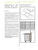
• A horizontal and vertical space of at least
20mm from the lower surface of the cooking
hob and at least 20mm from the downdraft
must be foreseen so as to create a passage
for the air necessary to cool the product (refer
to the above illustration).
• There must be an opening of at least 50mm
the whole width of the kitchen unit in the lower
and rear part of the furniture to allow for the
passage of air to avoid the product overheat-
ing.
• Ensure that the passage of air in the lower part
of the kitchen unit permits a constant flow of
air to cool the product.
• Fitting the oven underneath the cooking hob
is possible with fan-cooled ovens. Before in-
stalling the oven, remove the rear wall of the
kitchen unit where the oven will be fitted into
the kitchen furniture.
There must also be a minimum aperture of
5mm in the front part and above all in the low-
er part of the kitchen furniture to ensure an
adequate passage of air necessary to cool the
product.
Before installing the product, check that all com-
ponents are not damaged. If any components
are damaged, contact the retailer and do not go
ahead with the installation.
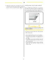
Before installing the downdraft, remove the safe-
ty spacer highlighted in the photograph (
Fig. 1
).
Furthermore, carefully read all the instructions as
follows:
• Utilise an air extraction duct that has a maxi-
mum length of not more than 5 metres.
• Limit the number of curves in the duct be-
cause each curve reduces the efficiency of the
extraction equal to 1 linear metre (E.g., if two
90° curves are utilised, the length of the duct
must not exceed 3 metres in length).
• Avoid drastic changes of direction.
• Utilise a duct with a 150mm or 200mm diam-
eter along its whole length.
• Utilise a duct that is manufactured from ma-
terial approved to the norm. The supplying
company will not respond to problems of flow
capacity or noise if there is a lack of respect of
the previously mentioned instructions and the
guarantee will be annulled.
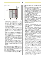
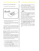
1. Position the support bracket of the down-
draft in the rear part of the realised aperture
(refer to
Fig. 2
).
2. The bracket must be positioned approxi-
mately two/three millimetres from the upper
surface of the worktop, as shown in
Fig.3
.
3. Fix the support bracket of the downdraft to
the worktop by utilising the screws supplied
in the case of wood worktops. For worktops
realised in materials different to wood, utilise
the appropriate screws.
4. Utilise the upper and lower holes positioned
in the support bracket of the downdraft in ac-
cordance with the thickness of the worktop
into which the product is installed.
5. Fix the two worktop reinforcement telescopic
structures to the lower sides of the support
bracket of the downdraft, as shown in
Fig. 4
.
6. After fixing the reinforcement structures, ad-
just their telescopic travel so as to reach the
base underneath (
Fig. 5
). Fix the structure
to the base underneath utilising the screws
supplied.
7. Check that the worktop is perfectly level then
block the travel of the structures utilising the four
self-threading screws, positioned as in
Fig. 6
.
8. Insert the downdraft into the installed sup-
port bracket (refer to
Fig. 7
). The fixtures
positioned on the downdraft must coincide
perfectly with the support bracket installed in
the kitchen unit (refer to
Fig. 8
).
Internal motor
Summary of Contents for DD931BK
Page 4: ...INDUCTION HOB 3 ...
Page 9: ...8 EN TECHNICAL DRAWING ...
Page 33: ...32 EN DOWNDRAFT ...
Page 40: ...40 IMAGES ...
Page 41: ...41 2 6 3 4 5 1 ...
Page 42: ...42 9 8 7 10 11 12 ...
Page 43: ...43 13 15 16 14 17 ...
Page 44: ...44 ...
Page 45: ...45 ...


