background image

N:  New adjustment item 
*1:  Only for disc label printing supported regions. 


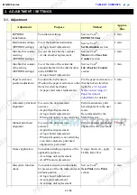
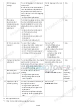
LCD language 
settings

To set the language to be displayed 
on the LCD. 
Not necessary when the machine is 
set to the default at shipment from 
the production site (On arrival at 
user's, the user is to set the language 
during setup.). 
- At logic board replacement 

Set the language in the user 
mode.

1 min.


Platen glass 
protection sheet 
(document pressure 
sheet) position 
adjustment

To maintain scanning accuracy, hold 
the sheet with the long side down, 
then fit its upper left corner to the 
platen glass reference mark (back 
left). 
- At protection sheet replacement 
- At FAU protection sheet 

replacement 

- At document pressure plate unit 

replacement 

- At scanner unit replacement 


1 min.


LF / Eject correction 
(manual)

To correct line feeding. 
- At paper feed roller  replacement 
- At platen unit replacement 
- At logic board replacement 
- At LF / EJ slit film replacement 
- At timing slit film replacement 

Service Tool

*2

(1) In the 

Print

 section, 

click 

LF/EJECT

(2) According to the printed 

pattern, set the 
correction value in the 

LF / EJECT 
Correction

 section. 

5 min.


Carriage rail position 
adjustment

To set the carriage rail to the original 
position prior to removal or 
replacement of the carriage unit, put 
a mark on the main chassis before 
removal of the carriage unit.

Put a mark using a sharp-
pointed metallic stick, such 
as a wimble. 

1 min.

   Disc label print 

position adjustment

*1

To set the center of disc label 
printing. 
- At logic board replacement 
- When printing shifts from the 

correct position 

Service Tool

*2

,  

CD-R Correction

 section

Varies 
depending 
on the 
degree of 
print shift.

N Capacitive sensor 

sensitivity setting

To correct variation in sensitivity of 
the capacitive sensors. 
- At logic board replacement 
- At document pressure plate unit 

replacement 

- When user complaints about the 

sensitivity of the operation panel 
arise 

Service Tool

*2

,  

Panel Rank

 section

5 min.

43 / 66

Summary of Contents for MG6110

Page 1: ...echnical inaccuracies or typographical errors due to improvements or changes made to the product When changes are made to the contents of the manual Canon will release technical information when neces...

Page 2: ...s Refer to the graphics in the separate Parts Catalog MG6100 series Troubleshooting Identify the problem and handle it accordingly Repair When a part needs to be replaced see this section Adjustment S...

Page 3: ...t right plate and switch system unit left plate removal 9 Engine unit reassembly 10 Cable wiring and connection 11 Ink absorber replacement 3 ADJUSTMENT SETTINGS 3 1 Adjustment 3 2 Adjustment and Main...

Page 4: ...eplacement of ink absorber 4 VERIFICATION AFTER REPAIR 4 1 Standard Inspection Flow 4 2 Integrated Inspection Pattern Print 4 3 Ink Absorber Counter Value Print 5 APPENDIX 5 1 Customer Maintenance 5 2...

Page 5: ...ogic board ass y The LCD does not display properly A portion of the LCD is not displayed The display flickers 1 Confirm cable connection LCD FFC Panel FFC No incomplete connection cable breakage or ca...

Page 6: ...jected Faint printing or white lines on printouts Uneven printing Improper color hue See 3 5 Special Notes on Servicing 1 For smeared printing uneven printing or non ejection of ink for details 1 Conf...

Page 7: ...EJ slit film 2 Replace the following item s Timing slit disk feed film or timing slit disk eject film Timing sensor unit Platen unit Logic board ass y Scanner unit for copying Smearing in disc label p...

Page 8: ...cancel the job at error occurrence and to clear the error 2 Confirm the network connection 3 Replace the following item s Logic board ass y Wireless LAN board ass y Error Error code U No Message on th...

Page 9: ...cannot be recognized Applicable ink tank icon Install the applicable ink tank s properly and confirm that the LED s of all the ink tanks light red Ink tank Carriage unit Print head not installed or no...

Page 10: ...djustment and Settings in Service Mode Pressing the OK button will exit the error and enable printing without replacing the ink absorber However when the ink absorber becomes full no further printing...

Page 11: ...ed Applicable ink tank icon A non supported ink tank is installed the ink tank LED is turned off Install the supported ink tanks Ink tank Ink tank not recognized 1682 U150 The following ink tank canno...

Page 12: ...clear the error Premium Contents print error 4100 Cannot print the data Install the supported Canon genuine ink tanks Ink tank Cycles of blinking of Alarm and Power LEDs Error Error code Check points...

Page 13: ...ge drive system unit Logic board ass y 5 times ASF cam sensor error 5700 1 Cable connection PE sensor cable Re connect the cable If any damage or breakage of the cable is found replace the cable ASF u...

Page 14: ...ormed replace the carriage unit 4 Cable connection CR FFC CN401 CN402 CN403 Re connect the cable If any damage or breakage of the cable is found replace the carriage unit AC adapter Carriage unit 11 t...

Page 15: ...ller sensor error 5C20 1 Cable connection Valve cam harness CN700 Re connect the cable Purge drive system unit 17 times Paper eject encoder error 6010 1 Smearing on the LF EJ slit film Clean the LF EJ...

Page 16: ...Scanner motor relay harness Lamp harness ass y FB motor error 5012 1 Cable connection FB motor harness CN902 Re connect the cables Scanner unit Scanner electric circuit error 5050 1 Cable connection C...

Page 17: ...ting occurs 5 Set the sensitivity of the capacitive sensors See 3 3 Adjustment and Settings in Service Mode 7 Capacitive sensor sensitivity setting for details 6 Print the EEPROM information See 3 3 A...

Page 18: ...e loosened only for paper feed motor replacement DO NOT loosen them in any other cases See 2 2 Part Replacement Procedures 8 Purge drive system unit right plate and switch system unit left plate remov...

Page 19: ...on for details In the service mode 2 Print the integrated inspection pattern Idler pulley parallel pin APP code wheel gear shaft Document pressure sheet 1 Cassette unit 2 Left and right side covers 3...

Page 20: ...ipe the film with ethanol Confirm no grease is on the film Wipe off any grease thoroughly with ethanol Do not bend the film In the user mode 1 Perform print head alignment In the service mode 2 Print...

Page 21: ...he paper feed motor may be loosened only at replacement of the paper feed motor unit DO NOT loosen them in other cases ii Before loosening the 3 screws that fix the carriage rail to the main chassis m...

Page 22: ...rd board IrDA board PE sensor board and WLAN board Some of the photos are of the MP630 and MP980 since their structures are same 1 External housing scanner unit and document cover removal MG6100 serie...

Page 23: ...e Be cautious of the core location and wiring layout 4 Remove the side cover L scanner unit then document pressure plate unit 3 screws While holding the scanner unit remove the side cover L then disen...

Page 24: ...5 Remove the main case no screws 20 66...

Page 25: ...ard to separate it from the scanner unit Through the slit of the scanner unit remove the panel cable 2 Remove the top cover from the base Peel off the document pressure sheet sponge sheet and remove 1...

Page 26: ...Release 3 claws 3 Separate the LCD unit and the power switch from the panel Cut the electrostatic protection sheet along the perforation and remove the protection sheet 22 66...

Page 27: ...In reassembling attach the new protection sheet as it is over the remaining portions of the sheet 23 66...

Page 28: ...iage unlocking 5 ASF unit removal 1 Rotate the APP motor drive gear in the red arrow direction in the left photo below to unlock the carriage Slide the carriage to the left the opposite of the home po...

Page 29: ...k the positions of the screws that fix the carriage upper rail to the main chassis 3 points for each screw the left right and center 3 Remove 3 screws that fix the carriage upper rail to the main chas...

Page 30: ...a flat blade screwdriver through the hole of the main chassis and press the carriage belt to release it from the pulley Be cautious to keep it free from any grease 7 Disconnect the carriage FFC from t...

Page 31: ...that the carriage unit will not contact the main chassis slowly lift the carriage unit to remove it from the main unit In assembling a new carriage unit follow the procedures in the reverse order For...

Page 32: ...hassis b upper and lower carriage rails and c carriage unit together just remove the screws from the left and right plates This way you just have to reassemble the set of units marking of the carriage...

Page 33: ...Unlock the paper eject roller gear While raising the front of the platen unit remove the platen unit from the printer unit 1 Release the springs of the carriage motor cable duplex printing paper feed...

Page 34: ...2 Remove the springs left and right from the pressure roller unit 3 Remove the screws that fix the units to the main chassis 3 on the left 2 on the right 30 66...

Page 35: ...the switch system unit and the purge drive system unit 1 Install the switch system unit in the bottom case while fitting the joint to the FD link unit then fasten the screws 3 screws Although the AC a...

Page 36: ...3 Attach the cassette feed guide 4 Install the cassette feed roller unit 32 66...

Page 37: ...paper feed belt and bushing then install them in the main unit 6 Attach the paper guide unit from above the paper feed roller along its bushing then hook the end of each spring on the protrusion of th...

Page 38: ...7 Install the platen unit and the spur unit 8 Connect the springs on each side of the spur holder to the switch system unit and the purge drive system unit respectively 34 66...

Page 39: ...and the release arm 2 arms 10 Fix the pressure roller unit to the main chassis screw it to the right and left plates 11 Attach the carriage unit to the carriage rail then align the carriage upper rail...

Page 40: ...the main chassis and fasten it with screws The carriage unit will be easy to be attached to the carriage rail when the lever is slid in the red arrowed direction in the photo below 36 66...

Page 41: ...ings in step 6 Springs hooked 13 While being cautious not to damage the carriage FFC install the front chassis and the ground chassis 14 Attach the ink sensor to the front chassis 15 Install the ASF u...

Page 42: ...he ink sensor cable inner cover open sensor cable WLAN harness and PictBridge FFC 3 Wiring on the left side Pass the ground cable through the hole to hook it on the side of the bottom case 1 Wiring on...

Page 43: ...the print unit from the bottom case It is not necessary to disassemble the whole engine unit 1 Disconnect the DC harness from the logic board right side of the machine 2 Disconnect the ground cable f...

Page 44: ...4 Slowly lift the print unit to separate it from the bottom case 40 66...

Page 45: ...e and each harness location return the print unit to the bottom case and fasten the screws 6 screws removed in step 3 8 Properly arrange and connect the harnesses install the scanner unit and attach t...

Page 46: ...d motor so that the belt is stretched tight See 3 5 Special Notes on Servicing 2 Paper feed motor adjustment for details 5 min Automatic print head alignment To secure the dot placement accuracy At pr...

Page 47: ...gic board replacement At LF EJ slit film replacement At timing slit film replacement Service Tool 2 1 In the Print section click LF EJECT 2 According to the printed pattern set the correction value in...

Page 48: ...ep cleaning consumes more ink than regular cleaning it is recommended to perform deep cleaning only when necessary Automatic print head alignment Perform via the machine operation panel or from the pr...

Page 49: ...the Alarm and Power LEDs light alternately iii When the Power LED lights the machine is ready for the service mode operation 2 Start the Service Tool on the connected computer i When a button is clic...

Page 50: ...arks 1 Test Print Service test print Paper will feed from the rear tray 2 sheets Printed items Model name ROM version USB serial number Process inspection information Barcode model name destination ma...

Page 51: ...ocess inspection information Barcode machine serial number Ink system function check result CD DVD sensor check result 5 EEPROM EEPROM information saving The EEPROM information is displayed on the com...

Page 52: ...nd click Set ASA AUS BRA CHN CND EMB EUR JPN KOR LTN TWN USA 16 CD R Correction Disc label print position correction X and Y direction To be used with 6 CD R check pattern print mainly in refurbishmen...

Page 53: ...returns to be ready for selection of another function A function was finished is displayed on the screen 3 In the printout determine the Pattern No in which streaks or lines are the least noticeable f...

Page 54: ...nts representing each button The color of a segment corresponding to the pressed button changes to red If 2 or more buttons are pressed at the same time only one of them is considered to be pressed an...

Page 55: ...nter section of the Service Tool select Main from the Absorber pull down menu From the Counter Value pull down menu select the value in 10 increments which is the closest to the actual counter value c...

Page 56: ...he sensitivity is low the panel is slow to respond select 0 zero When the sensitivity is high the panel is quick to respond select 3 For reference Measure the sensitivity as follows Put your finger 2...

Page 57: ...the carriage unit slides 1 Floil KG107A 230 to 290 2 Carriage rail The surface where the carriage unit slides 2 Floil KG107A 180 to 220 3 Carriage rail The surface where the carriage unit slides 3 Flo...

Page 58: ...54 66...

Page 59: ...ozzle check pattern is not printed properly the print head may be faulty Perform troubleshooting while referring to the Print Head Workshop Manual or the Print Head Service Manual 1 4 Troubleshooting...

Page 60: ...ference point on the platen glass back left where the red lines cross in the photo above 2 Slowly close the document pressure plate while maintaining the hinge position The document pressure sheet wil...

Page 61: ...24 months or more No need to replace the ink absorber Note If the ST installation date value is 2010 07 31 or earlier the DF ink absorber life value may not be correct Skip Step 2 The ink absorber li...

Page 62: ...sheet or scanner unit replacement Communication with a connected computer Check point Via USB connection to the computer printing from the computer must be performed properly paper feeding from the re...

Page 63: ...4 2 Integrated Inspection Pattern Print Print sample 59 66...

Page 64: ...4 3 Ink Absorber Counter Value Print Print sample 4 VERIFICATION AFTER REPAIR 60 66...

Page 65: ...nt head deep cleaning When print quality is not satisfying and not improved by print head cleaning To improve nozzle conditions Computer printer driver 2 min Ink tank replacement When an ink tank beco...

Page 66: ...r error Paper feeding problem 6 APP encoder sensor Detects rotation of the APP encoder and controls paper feeding from the rear tray and from the cassette and purging operation APP sensor error APP po...

Page 67: ...Pump roller sensor Detects the position of the pump roller and controls purging operation Pump roller sensor error 14 Purge cam sensor Detects the position of the purge main cam and controls purging...

Page 68: ...64 66...
Page 69: ...On the inner guide over the upper portion of the spur holder visible when the scanning unit cover is opened The photos are for the MP990 as examples When the machine power is OFF When the machine pow...

Page 70: ...See Caution 2 below If the print head must be removed from the machine and transported alone attach the protective cap used when the packing was opened to the print head to protect the print head fac...

Reviews: