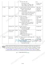
(5) Main case
(6) Rear cover
(7) Print unit
(8) See
2-2. Part Replacement Procedures
.
- DO NOT contact the spur edges.
(only when uneven printing or
streaks appear on printouts after
replacement).
[See
3-3. Adjustment and
Settings in Service Mode
, for
details.]
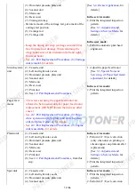
Purge drive
system unit
(1) Cassette unit
(2) Left and right side covers
(3) Document pressure plate unit
(4) Scanner unit
(5) Main case
(6) Rear cover
(7) Print unit
(8) See
2-2. Part Replacement Procedures
.
- See
2-2. Part Replacement Procedures, (8) Purge
drive system unit (right plate) and switch system
unit (left plate) removal
, for details.
- See
2-2. Part Replacement Procedures, (9) Engine
unit reassembly
, for details.
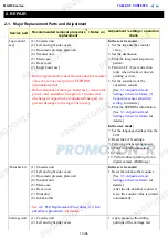
In the service mode:
1. Print the integrated inspection
pattern.
Carriage rail
and main
chassis
See
2-2. Part Replacement Procedures
, and Parts
Catalog.
1. Apply grease to the sliding
portions.
[See
3-4. Grease Application
, for
details.]
In the service mode:
2. Print the integrated inspection
pattern.
Idler pulley
parallel pin
APP code
wheel gear
shaft
Document
pressure sheet
(1) Cassette unit
(2) Left and right side covers
(3) Document pressure plate unit
(4) Scanner unit
1. Confirm the document pressure
plate sheet position.
[See
3-5. Special Notes on
Servicing, (4) Document
pressure sheet replacement
, for
details.]
In the service mode:
2. Print the integrated inspection
pattern.
Document
pressure plate
Scanner unit
Document
pressure plate
unit
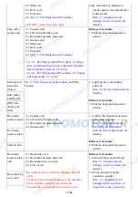
(1) Right side cover
(2) Document pressure plate unit
(3) Document top cover unit
(4) LCD viewer
- Be cautious not to scratch or damage the LCD
cable.
- To protect the external housing of the machine
from scratches, spread a soft cloth and
disassemble / reassemble the machine on it.
In the service mode:
1. Perform button and LCD test.
[See
3-3. Adjustment and
Settings in Service Mode
, for
details.]
2. Set the sensitivity of the
capacitive sensors.
[See
3-3. Adjustment and
Settings in Service Mode, (7)
Capacitive sensor sensitivity
Document top
cover unit
15 / 66
Summary of Contents for MG6110
Page 24: ...5 Remove the main case no screws 20 66...
Page 36: ...3 Attach the cassette feed guide 4 Install the cassette feed roller unit 32 66...
Page 44: ...4 Slowly lift the print unit to separate it from the bottom case 40 66...
Page 58: ...54 66...
Page 63: ...4 2 Integrated Inspection Pattern Print Print sample 59 66...
Page 64: ...4 3 Ink Absorber Counter Value Print Print sample 4 VERIFICATION AFTER REPAIR 60 66...
Page 68: ...64 66...

