instead of the E-MIP correction value (thus, in the initial EEPROM information print, "LF = *"
and "EJ = *" are printed, but the selected values are printed after the LF / Eject correction).
(4) Button and LCD test
Confirm the operation after replacement of the operation panel unit, panel board, or LCD.
1) Check to see if the LED turns off properly
1-1) Click
Panel Check
of the Service Tool. All the LED's on the machine turn on and the LCD turns blue,
waiting for a button to be pressed.
1-2) Press the OK button multiple number of times, and confirm that the LED turns off in the following order
from No. 1 to No. 20 each time the OK button is pressed:
1-3) Press the OK button. The machine becomes ready for the next operation.
2) Button check
2-1) Press each button of the operation panel, to see if every button functions properly.
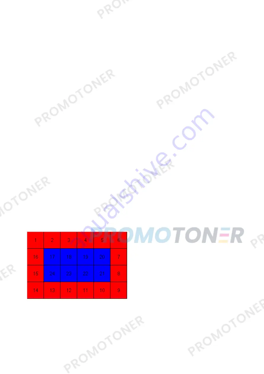
2-2) The LCD is divided into 24 segments, representing each button. The color of a segment corresponding to
the pressed button changes to red. If 2 or more buttons are pressed at the same time, only one of them is
considered to be pressed, and the other buttons are ignored.
2-3) Press the OK button. The machine becomes ready for the next operation.
3) LCD data line short / open check
3-1) The RGB gradation pattern is displayed on the LCD. Visually confirm that the patterns are displayed
properly.
No.
No.
1. left function button
2. center function button
3. right function button
4. "Start" text
5. "Stop" text
6. Stop button
7. Color button
8. Black button
9. + - buttons
10. Scroll Wheel
11. up cursor
12. right cursor
13. down cursor
14. left cursor
15. Back button
16. HOME button
17. Power lamp
18. Alarm lamp
19. Wi-Fi lamp
20. OK button
1. ON button
2. Back button
3. OK button
4. up cursor button
5. down cursor button
6. left cursor button
7. right cursor button
8. Black button
9. Color button
10. Stop button
11. HOME button
12. left function button
13. center function button
14. right function button
15. +
16. -
50 / 66
Summary of Contents for MG6110
Page 24: ...5 Remove the main case no screws 20 66...
Page 36: ...3 Attach the cassette feed guide 4 Install the cassette feed roller unit 32 66...
Page 44: ...4 Slowly lift the print unit to separate it from the bottom case 40 66...
Page 58: ...54 66...
Page 63: ...4 2 Integrated Inspection Pattern Print Print sample 59 66...
Page 64: ...4 3 Ink Absorber Counter Value Print Print sample 4 VERIFICATION AFTER REPAIR 60 66...
Page 68: ...64 66...


