


4
4
4-102
4-102
Disassembly/Assembly > Controller System > Removing the FAX-NCU PCB Models with FAX (100V)
Disassembly/Assembly > Controller System > Removing the FAX-NCU PCB Models with FAX (100V)
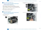
Before Removing the Main Controller PCB
Model without FAX, with NET (MF4420n)
1) Remove the left cover. (Single-sided models) (Refer to page 4-32)
Removing the Main Controller PCB
Model without FAX, with NET (MF4420n)
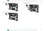
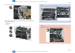
1) Remove the 3 flat cables [1] and 1 connector [2].
x4
[1]
[2]
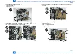
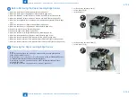
2) Remove the main controller PCB [1].
• 1 screw (binding) [2]
• 5 screws (black TP) [3]
[1]
[2]
[3]
[3]
x6
F-4-246
F-4-247
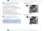
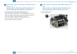
Before Removing the FAX-NCU PCB
Models with FAX (100V)
1-1) Remove the left cover. (Duplex models) (Refer to page 4-31)
1-2) Remove the left cover. (Single-sided models) (Refer to page 4-32)
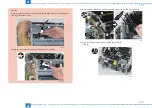
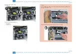
Removing the FAX-NCU PCB
Models with FAX (100V)
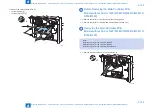
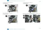
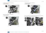
1) Remove the FAX-NCU PCB [1].
• 1 flat cable [2]
• 3 connectors [3]
• 1 terminal [4]
• 3 screws (black TP) [5]
[4] [5]
[5]
x3
x5
[1]
[2]
[3]
[3]
F-4-248
Summary of Contents for MF4500 Series
Page 222: ...5 5 Adjustment Adjustment Mechanical Adjustment ...
Page 224: ...6 6 Trouble Shooting Trouble Shooting Test Print Trouble Shooting Items Version Upgrade ...
Page 230: ...7 7 Error Codes Error Codes Overview Error Codes ...
Page 234: ...8 8 Service Mode Service Mode Overview COPIER FEEDER FAX TESTMODE ...
Page 251: ... Service Tools Solvent Oil List General Circuit Diagram General Timing Chart Appendix ...


