


4
4
4-82
4-82
Disassembly/Assembly > Controller System > Removing the Drive Belt Duplex models (MF4580dn/MF4570dn/MF4550d/MF4553d/MF4554d/D550/D520)
Disassembly/Assembly > Controller System > Removing the Drive Belt Duplex models (MF4580dn/MF4570dn/MF4550d/MF4553d/MF4554d/D550/D520)
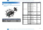
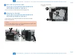
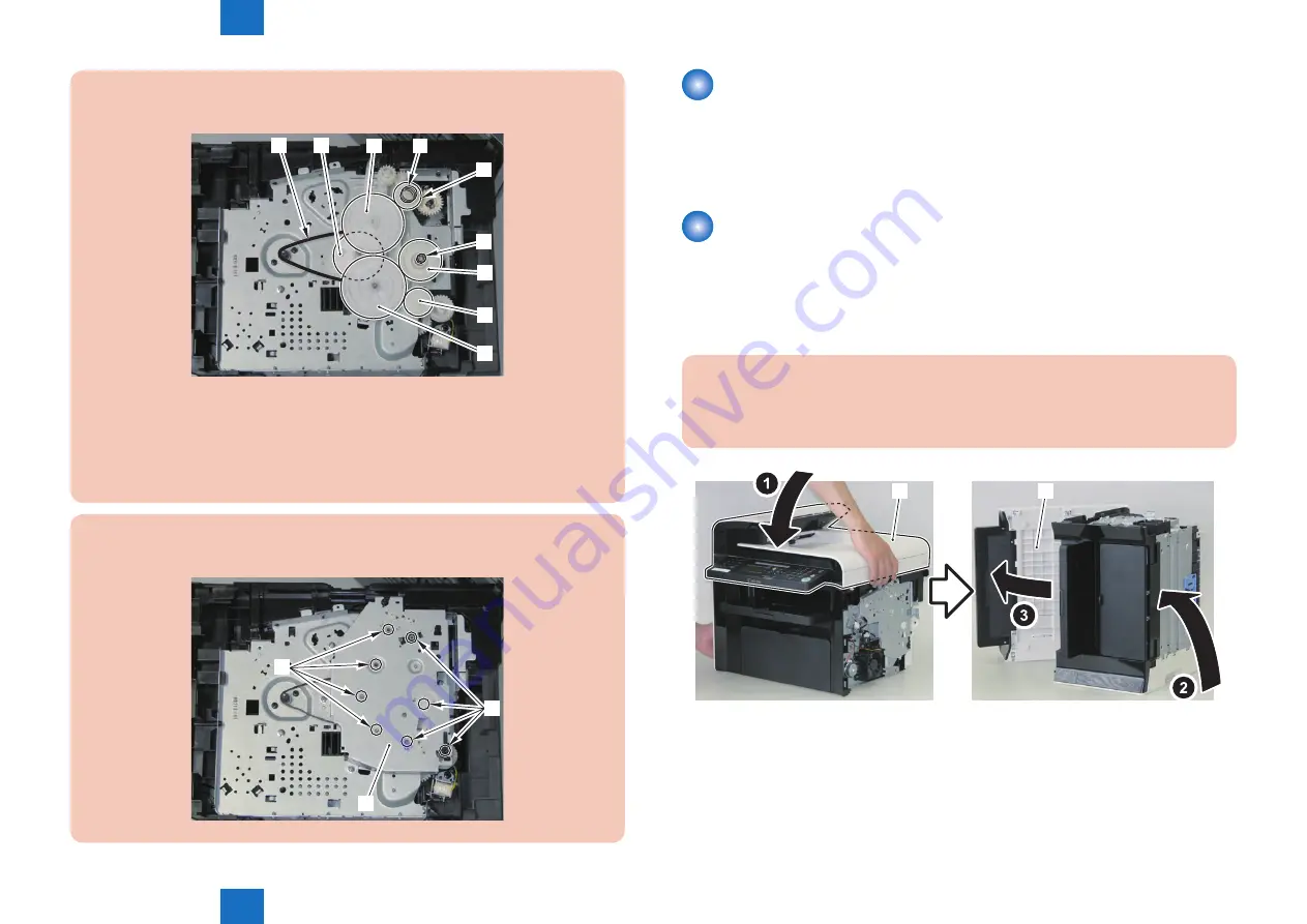
Caution:
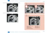
Assemble the drive gear in the order shown in the below picture.
[1]
[2]
[4]
[8]
[3]
[9]
[6]
[7]
[5]
[1] Primary deceleration pulley
[6] Gear coupling
[2] Timing belt
[7] Feed deceleration gear
[3] Fixing ratchet gear
[8] Compression spring
[4] Fixing transmission gear
[9] Compression spring
[5] Cartridge transmission gear
F-4-186
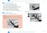
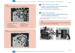
Caution:
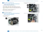
Align the drive cover [2] with the 8 shaft holes [1] to mount it.
[1]
[2]
[1]
F-4-187
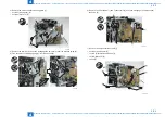
Before Removing the Drive Belt
Duplex models (MF4580dn/MF4570dn/MF4550d/
MF4553d/MF4554d/D550/D520)
1) Remove the right cover. (Duplex models) (Refer to page 4-33)
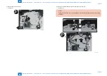
Removing the Drive Belt
Duplex models (MF4580dn/MF4570dn/MF4550d/
MF4553d/MF4554d/D550/D520)
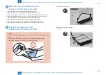
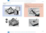
1) Close the reader unit [1] and face the left side of the host machine downwards.
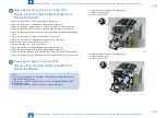
2) Open the reader unit [1].
Caution:
Take care when facing the left side of the host machine downwards because the reader
unit [1] will be forced open by hinge spring pressure.
[1]
[1]
F-4-188
Summary of Contents for MF4500 Series
Page 222: ...5 5 Adjustment Adjustment Mechanical Adjustment ...
Page 224: ...6 6 Trouble Shooting Trouble Shooting Test Print Trouble Shooting Items Version Upgrade ...
Page 230: ...7 7 Error Codes Error Codes Overview Error Codes ...
Page 234: ...8 8 Service Mode Service Mode Overview COPIER FEEDER FAX TESTMODE ...
Page 251: ... Service Tools Solvent Oil List General Circuit Diagram General Timing Chart Appendix ...


