Power Supply
Outline
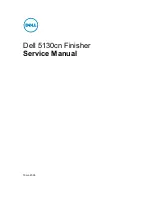
When the host machine is turned on, it supplies the finisher controller PCB with 24 VDC and 5 VDC. The 24 VDC power is used
to drive the motors, solenoid and the switches, while the 5 VDC power is for the sensors and the like.
Stapler Motor
Stack Tray
Paper Height Sensor
Sensors
PS1 to PS8
PS10 to PS16
Front Cover Switch
Motors
M1 to M7
M9 to M10
M
CPU(IC1)
F1
5VDC
+3.3VDC
24VDC
F3
F2
MSW1
M8
PS9
Paper Trailing Edge
Pushing Guide Solenoid
SL1
F4
Host
machine
+3.3V
generation
circuit
Finisher Controller PCB (PCB1)
Protective Functions
The finisher controller PCB is provided with fuses (F1 through 4) which blow in response to overcurrent.
2. Technical Explanation
37
Summary of Contents for Inner Finisher-L1
Page 11: ...Product Overview 1 Features 5 Specifications 6 Name of Parts 9 ...
Page 46: ...Periodical Service 3 List of Work for Scheduled Servicing 40 ...
Page 58: ...1x 1x 1 2 5 Remove the Interface Cover 1 2 Claws 2 1 2 4 Parts Replacement and Cleaning 51 ...
Page 122: ...Troubleshooting 6 Making Initial Checks 116 Processing Tray Area 117 ...
Page 126: ...APPENDICES Service Tools 120 General Circuit Diagram 121 ...