


Chapter 16
16-12
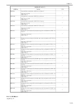
6.ERR
F-16-11
- <No.> Error occurrence order number
1 to 50 (The larger the number is, the older the error is.)
- <Date> Error occurrence date
- <TIME1> Error occurrence time
- <TIME2> Error recovery time
- <CODE> Error code
- <DTL> Detailed code (When there is no detailed code, "0000" is displayed.)
- <L> Occurrence category
T-16-11
- <P> Not used
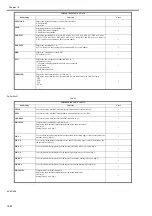
7.HV-STS
T-16-12
0042
post-separation sensor
PI7
1st; stationary jam at the post-separation sensor
0043
registration sensor
PI1
1st; not reaching the registration sensor
0044
registration sensor
PI1
1st; stationary at the registration sensor
0045
feed sensor
PI8
1st; not reaching the read sensor
0046
feed sensor
PI8
1st; stationary at the read sensor
0047
delivery reversal sensor
PI9
1st; not reaching heat delivery sensor
0048
delivery reversal sensor
PI9
1st; stationary sensor at the delivery sensor
0071
wrong timing
-
error software timing
0073
wrong timing
-
the shift motor is faulty
0090
ADF open/closed sensor 1
PS502
the ADF is opened during operation
0091
ADF open/closed sensor 1
PS502
the ADF is opened during operation (while paper is in wait)
0092
DF cover open/closed sensor
PI6
A cover is opened during operation (while a drive mechanism is in operation).
0093
DF cover pen/closed sensor
PI6
A cover is opened during operation (in wait for paper).
0094
registration sensor, separation
sensor, feed sensor, delivery
reversal sensor
PI1,PI7,PI8,PI9 Paper is detected in the path while the 1st sheet is being picked up.
0095
original placement sensor, DF
cover open/closed sensor, ADF
open/closed sensor 1
PI5,PI6,PS502
A signal arrives indicating the start of pickup in the absence of an original in the tray or while
the machine is in an OPEN state.
Location Classification
0
main controller
1
Feeder
2
finisher
3
not used
4
reader unit
5
printer unit
6
PDL board (any of)
7
fax board
COPIER>DISPLAY>HV-STS
Subheading
Contents
Level
PRI-GRID
Grid voltage of the primary charging assembly (Unit: V)
1
Code
Sensor type
Sensor notation
Description
Summary of Contents for imagePRESS C1
Page 1: ...Oct 22 2008 Service Manual imagePRESS C1 Series ...
Page 2: ......
Page 6: ......
Page 38: ...Contents ...
Page 39: ...Chapter 1 Introduction ...
Page 40: ......
Page 42: ......
Page 72: ...Chapter 1 1 30 F 1 18 ...
Page 85: ...Chapter 1 1 43 T 1 26 ...
Page 88: ......
Page 89: ...Chapter 2 Installation ...
Page 90: ......
Page 94: ......
Page 234: ......
Page 235: ...Chapter 3 Basic Operation ...
Page 236: ......
Page 238: ......
Page 244: ......
Page 245: ...Chapter 4 Main Controller ...
Page 246: ......
Page 248: ......
Page 276: ...Chapter 5 Original Exposure System ...
Page 277: ......
Page 332: ...Chapter 6 Laser Exposure ...
Page 333: ......
Page 342: ...Chapter 6 6 8 F 6 10 1 Laser Light 2 Laser Shutter 3 Laser Shutter Lever 1 1 2 2 1 2 3 3 3 3 ...
Page 344: ...Chapter 7 Image Formation ...
Page 345: ......
Page 431: ...Chapter 7 7 82 ...
Page 462: ...Chapter 8 Pickup Feeding System ...
Page 463: ......
Page 504: ...Chapter 8 8 39 7 F 8 52 8 F 8 53 9 F 8 54 1 3 2 1 2 4 3 1 2 4 3 ...
Page 505: ...Chapter 8 8 40 10 F 8 55 11 F 8 56 12 F 8 57 1 4 2 3 5 4 1 3 2 1 4 2 5 3 ...
Page 506: ...Chapter 8 8 41 13 F 8 58 14 F 8 59 15 F 8 60 5 1 2 3 4 1 2 3 5 4 1 2 3 4 5 ...
Page 507: ...Chapter 8 8 42 16 F 8 61 1 2 3 4 5 ...
Page 509: ...Chapter 8 8 44 3 F 8 64 A Duplexing reversal position 4 F 8 65 2 1 A 2 1 ...
Page 510: ...Chapter 8 8 45 5 F 8 66 6 F 8 67 2 1 2 1 ...
Page 511: ...Chapter 8 8 46 7 F 8 68 8 F 8 69 3 2 1 3 2 1 ...
Page 512: ...Chapter 8 8 47 9 F 8 70 10 F 8 71 3 2 1 2 3 1 ...
Page 513: ...Chapter 8 8 48 11 F 8 72 B Duplexing re pickup stop position 12 F 8 73 3 2 B 1 3 1 2 ...
Page 514: ...Chapter 8 8 49 13 F 8 74 14 F 8 75 1 2 3 1 2 3 ...
Page 516: ...Chapter 8 8 51 F 8 77 SL3 M10 PS17 ...
Page 533: ...Chapter 8 8 68 F 8 154 1 2 4 3 2 3 4 ...
Page 534: ...Chapter 9 Fixing System ...
Page 599: ...Chapter 10 Externals and Controls ...
Page 642: ...Chapter 11 MEAP ...
Page 643: ......
Page 645: ......
Page 695: ...Chapter 12 Maintenance and Inspection ...
Page 696: ......
Page 698: ......
Page 700: ...Chapter 12 12 2 F 12 1 28 9 10 14 13 29 29 11 12 27 6 3 1 2 5 4 7 8 15 16 ...
Page 701: ...Chapter 12 12 3 F 12 2 17 20 24 23 25 26 19 18 24 21 22 ...
Page 704: ...Chapter 12 12 6 F 12 3 1 2 3 4 9 6 5 7 8 11 12 13 14 15 10 ...
Page 715: ...Chapter 12 12 17 F 12 18 1 1 2 2 ...
Page 716: ...Chapter 13 Standards and Adjustments ...
Page 717: ......
Page 719: ......
Page 732: ...Chapter 14 Correcting Faulty Images ...
Page 862: ...Chapter 15 Self Diagnosis ...
Page 894: ...Chapter 16 Service Mode ...
Page 895: ......
Page 1222: ...Chapter 17 Upgrading ...
Page 1223: ......
Page 1225: ......
Page 1256: ...Chapter 17 17 31 F 17 65 2 Turn off the main power switch and remove the USB device ...
Page 1257: ...Chapter 18 Service Tools ...
Page 1262: ......
Page 1263: ......
Page 1264: ...Oct 22 2008 ...
Page 1265: ......


