


Chapter 2
2-70
el.
11) Press 'Start scan'. In a response, the test print 2 will be read.
12) When the control panel shows the message that orders removal of the test
print, remove the test print 2 from the copyboard glass.
13) Press 'Test print 3'. In a response, the test print 3 will be printed.
14) Place the test print 3 on the copyboard glass by following the control pan-
el.
15) Press 'Start scan'. In a response, the test print 3 will be read.
16) When the control panel shows the message that orders removal of the test
print, remove the test print 3 from the copyboard glass.
17) Exit from 'Additional Functions' screen.
2.2.38 Automatic Gradation Correction Setting
0013-7865
imagePRESS C1 P / imagePRESS C1+ (Printer)
1) Select Initial Additional Functions > System Settings > Device Manage-
ment Settings > Auto Gradation Adjustment.
2) Select 'Full Adjust'.
3) Select the source of paper for test print and press 'OK'.
4) Press 'start'.
5) Exit from 'Additional Functions' screen.
2.2.39 Checking a Clear Color Image
0020-4624
imagePRESS C1+ (Printer) / imagePRESS C1+
1) Set paper (A4/LTR) in the cassette 1.
2) Select a service mode item (COPIER > TEST > PG > TYPE) and enter 14.
3) Select a service mode item (COPIER > TEST > PG > F/M-SW) and enter
3.
4) Press the [Start] button and perform a test print.
2.2.40 Checking Image / Operation
0012-7687
imagePRESS C1 P / imagePRESS C1 / imagePRESS C1+ (Printer) / image-
PRESS C1+
1) Place the test chart (CANON CA-1 TEST SHEET) on the copyboard.
Feed paper from each cassette and check the image.
- Check to be sure that there is no unusual sound.
- Check to be sure the image quality with each default magnification.
- Check to be sure that the behavior to print the specified number of sheets
is normal.
- Check to be sure that the image printed from each cassette is within the
range of the standard value.
There are 2 standard values as follows:
Standard value of left margin of image: 2.5 +/- 1.5 mm
Standard value of margin along leading edge of image: 3.0 +1.5/-1.0 mm
2.2.41 Adjusting Left Margin of Image
0012-9075
imagePRESS C1 P / imagePRESS C1 / imagePRESS C1+ (Printer) / image-
PRESS C1+
Adjusting methods of left margin of image in accordance with each pickup
slot are described below.
1. Adjusting Method of Cassette
1) Press the cassette release button, and pull out the cassette toward the front.
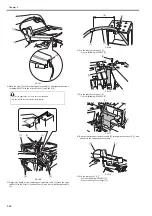
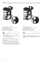
2) Open the upper right cover and the lower right cover.
3) Insert the screwdriver from the hole of the right front crossmember. Loos-
en the screw [1] and adjust the position of the adjusting plate [2].
F-2-229
Move the slide guide toward the rear = left margin decreases
Move the slide guide toward the front = left margin increases
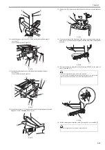
4) Tighten the screw.
5) Close the upper right cover and the lower right cover.
6) Put back the cassette.
7) Check to be sure that the left margin of images printed from each cassette
are within L1 = 2.5 +/-1.5 mm.
F-2-230
[1] Feeding direction of paper
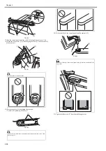
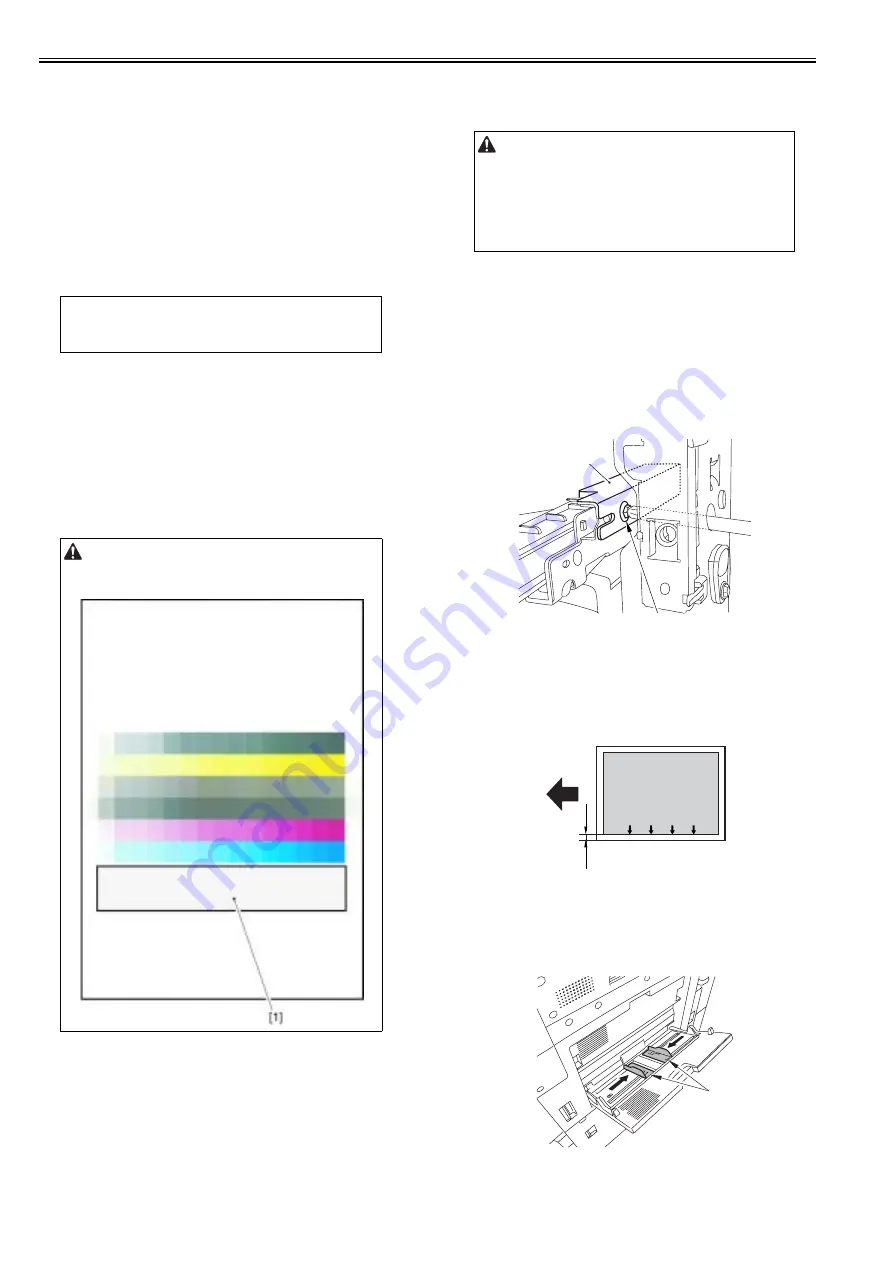
2. Adjusting Method of Manual Feed Tray
1) Open the manual feed tray.
2) Slide the side guide plate[1] in the direction of the arrow.
F-2-231
3) Loosen the screw [1], and adjust the left margin of image by moving the
MEMO:
When attaching the reader (accessory) at the same time, there are selections
available to execute as an auto gradation correction method from 'Auto
Gradation Adjust Method': either 'Printer Only' or 'S printer'.
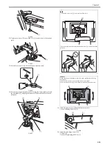
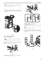
Print a 5-full-color 16-gradation test pattern, and make sure that there is no
color mixture in the clear area [1].
When the value is not within the standard value, refer to 'Adjusting left
margin of image' or 'Adjusting margin along leading edge of image'.
In the case of image fault (vertical/horizontal lines), see the item for
'cleaning the charging assembly'.
[1]
[2]
image
L1
[1]
[1]
Summary of Contents for imagePRESS C1
Page 1: ...Oct 22 2008 Service Manual imagePRESS C1 Series ...
Page 2: ......
Page 6: ......
Page 38: ...Contents ...
Page 39: ...Chapter 1 Introduction ...
Page 40: ......
Page 42: ......
Page 72: ...Chapter 1 1 30 F 1 18 ...
Page 85: ...Chapter 1 1 43 T 1 26 ...
Page 88: ......
Page 89: ...Chapter 2 Installation ...
Page 90: ......
Page 94: ......
Page 234: ......
Page 235: ...Chapter 3 Basic Operation ...
Page 236: ......
Page 238: ......
Page 244: ......
Page 245: ...Chapter 4 Main Controller ...
Page 246: ......
Page 248: ......
Page 276: ...Chapter 5 Original Exposure System ...
Page 277: ......
Page 332: ...Chapter 6 Laser Exposure ...
Page 333: ......
Page 342: ...Chapter 6 6 8 F 6 10 1 Laser Light 2 Laser Shutter 3 Laser Shutter Lever 1 1 2 2 1 2 3 3 3 3 ...
Page 344: ...Chapter 7 Image Formation ...
Page 345: ......
Page 431: ...Chapter 7 7 82 ...
Page 462: ...Chapter 8 Pickup Feeding System ...
Page 463: ......
Page 504: ...Chapter 8 8 39 7 F 8 52 8 F 8 53 9 F 8 54 1 3 2 1 2 4 3 1 2 4 3 ...
Page 505: ...Chapter 8 8 40 10 F 8 55 11 F 8 56 12 F 8 57 1 4 2 3 5 4 1 3 2 1 4 2 5 3 ...
Page 506: ...Chapter 8 8 41 13 F 8 58 14 F 8 59 15 F 8 60 5 1 2 3 4 1 2 3 5 4 1 2 3 4 5 ...
Page 507: ...Chapter 8 8 42 16 F 8 61 1 2 3 4 5 ...
Page 509: ...Chapter 8 8 44 3 F 8 64 A Duplexing reversal position 4 F 8 65 2 1 A 2 1 ...
Page 510: ...Chapter 8 8 45 5 F 8 66 6 F 8 67 2 1 2 1 ...
Page 511: ...Chapter 8 8 46 7 F 8 68 8 F 8 69 3 2 1 3 2 1 ...
Page 512: ...Chapter 8 8 47 9 F 8 70 10 F 8 71 3 2 1 2 3 1 ...
Page 513: ...Chapter 8 8 48 11 F 8 72 B Duplexing re pickup stop position 12 F 8 73 3 2 B 1 3 1 2 ...
Page 514: ...Chapter 8 8 49 13 F 8 74 14 F 8 75 1 2 3 1 2 3 ...
Page 516: ...Chapter 8 8 51 F 8 77 SL3 M10 PS17 ...
Page 533: ...Chapter 8 8 68 F 8 154 1 2 4 3 2 3 4 ...
Page 534: ...Chapter 9 Fixing System ...
Page 599: ...Chapter 10 Externals and Controls ...
Page 642: ...Chapter 11 MEAP ...
Page 643: ......
Page 645: ......
Page 695: ...Chapter 12 Maintenance and Inspection ...
Page 696: ......
Page 698: ......
Page 700: ...Chapter 12 12 2 F 12 1 28 9 10 14 13 29 29 11 12 27 6 3 1 2 5 4 7 8 15 16 ...
Page 701: ...Chapter 12 12 3 F 12 2 17 20 24 23 25 26 19 18 24 21 22 ...
Page 704: ...Chapter 12 12 6 F 12 3 1 2 3 4 9 6 5 7 8 11 12 13 14 15 10 ...
Page 715: ...Chapter 12 12 17 F 12 18 1 1 2 2 ...
Page 716: ...Chapter 13 Standards and Adjustments ...
Page 717: ......
Page 719: ......
Page 732: ...Chapter 14 Correcting Faulty Images ...
Page 862: ...Chapter 15 Self Diagnosis ...
Page 894: ...Chapter 16 Service Mode ...
Page 895: ......
Page 1222: ...Chapter 17 Upgrading ...
Page 1223: ......
Page 1225: ......
Page 1256: ...Chapter 17 17 31 F 17 65 2 Turn off the main power switch and remove the USB device ...
Page 1257: ...Chapter 18 Service Tools ...
Page 1262: ......
Page 1263: ......
Page 1264: ...Oct 22 2008 ...
Page 1265: ......


