


Chapter 7
7-92
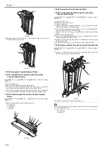
F-7-151
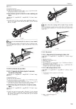
2) Detach the seal support plate (rear) [1].
- 2 screws [2]
F-7-152
When Mounting the Seal Support Plate (Front/Rear)
- When mounting the seal support plate (front/rear), make the seal support
plate [2] on the scoop-up sheet [1].
F-7-153
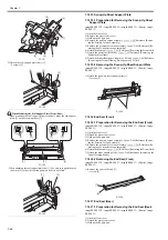
- When attaching the seal support plate (rear) [1], be sure to support the area
shown in [2] so that the seal support plate (rear) is not tilted.
F-7-154
7.14.15 Scoop-Up Sheet Support Plate
7.14.15.1 Preparation for Removing the Scoop-Up Sheet
Support Plate
0013-9790
imagePRESS C1 P / imagePRESS C1 / imagePRESS C1+ (Printer) / image-
PRESS C1+
1) Open the front cover.
2) Remove the process unit cover.
3) Hold up the hopper unit.
4) Remove the primary corona assembly.
Reference [Remov-
ing the Primary Corona Assembly]
5) Remove the pre-transfer corona assembly.
Reference [Re-
moving the pre-transfer corona assembly]
6) Detach the drum unit.
Reference [Removing the Drum Unit]
7) Detach the photosensitive drum.
Reference [Removing the
Photosensitive Drum]
8) Detach the drum cleaning pre-exposure LED unit.
[Removing the Drum Cleaning Pre-Exposure LED Unit]
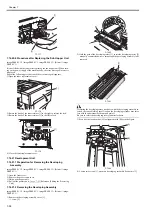
7.14.15.2 Removing the Scoop-Up Sheet Support Plate
0013-9791
imagePRESS C1 P / imagePRESS C1 / imagePRESS C1+ (Printer) / image-
PRESS C1+
1) Detach the scoop-up sheet support plate [1].
- 2 screws [2]
F-7-155
7.14.16 End Seal (Front)
7.14.16.1 Preparation for Removing the End Seal (Front)
0013-9741
imagePRESS C1 P / imagePRESS C1 / imagePRESS C1+ (Printer) / image-
PRESS C1+
1) Open the front cover.
2) Detach the process unit cover.
3) Hold up the hopper unit.
4) Remove the primary corona assembly.
Reference [Remov-
ing the Primary Corona Assembly]
5) Remove the pre-transfer corona assembly.
Reference [Re-
moving the pre-transfer corona assembly]
6) Detach the drum unit.
Reference [Removing the Drum Unit]
7) Detach the drum cleaning blade.
Reference [Removing the
Drum Cleaning Blade]
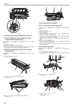
7.14.16.2 Removing the End Seal (Front)
0013-9742
imagePRESS C1 P / imagePRESS C1 / imagePRESS C1+ (Printer) / image-
PRESS C1+
1) Remove the end seal (front) [1].
- 1 screw [2]
F-7-156
7.14.17 End Seal (Rear)
7.14.17.1 Preparation for Removing the End Seal (Rear)
0013-9743
imagePRESS C1 P / imagePRESS C1 / imagePRESS C1+ (Printer) / image-
PRESS C1+
1) Open the front cover.
2) Detach the process unit cover.
3) Hold up the hopper unit.
[2]
[3]
[4]
[4]
[4]
[1]
[2]
[2]
[1]
[1]
[2]
[1]
[1]
[1]
[2]
[1]
[2]
[1]
[1]
[2]
[2]
[1]
Summary of Contents for imagePRESS C1
Page 1: ...Oct 22 2008 Service Manual imagePRESS C1 Series ...
Page 2: ......
Page 6: ......
Page 38: ...Contents ...
Page 39: ...Chapter 1 Introduction ...
Page 40: ......
Page 42: ......
Page 72: ...Chapter 1 1 30 F 1 18 ...
Page 85: ...Chapter 1 1 43 T 1 26 ...
Page 88: ......
Page 89: ...Chapter 2 Installation ...
Page 90: ......
Page 94: ......
Page 234: ......
Page 235: ...Chapter 3 Basic Operation ...
Page 236: ......
Page 238: ......
Page 244: ......
Page 245: ...Chapter 4 Main Controller ...
Page 246: ......
Page 248: ......
Page 276: ...Chapter 5 Original Exposure System ...
Page 277: ......
Page 332: ...Chapter 6 Laser Exposure ...
Page 333: ......
Page 342: ...Chapter 6 6 8 F 6 10 1 Laser Light 2 Laser Shutter 3 Laser Shutter Lever 1 1 2 2 1 2 3 3 3 3 ...
Page 344: ...Chapter 7 Image Formation ...
Page 345: ......
Page 431: ...Chapter 7 7 82 ...
Page 462: ...Chapter 8 Pickup Feeding System ...
Page 463: ......
Page 504: ...Chapter 8 8 39 7 F 8 52 8 F 8 53 9 F 8 54 1 3 2 1 2 4 3 1 2 4 3 ...
Page 505: ...Chapter 8 8 40 10 F 8 55 11 F 8 56 12 F 8 57 1 4 2 3 5 4 1 3 2 1 4 2 5 3 ...
Page 506: ...Chapter 8 8 41 13 F 8 58 14 F 8 59 15 F 8 60 5 1 2 3 4 1 2 3 5 4 1 2 3 4 5 ...
Page 507: ...Chapter 8 8 42 16 F 8 61 1 2 3 4 5 ...
Page 509: ...Chapter 8 8 44 3 F 8 64 A Duplexing reversal position 4 F 8 65 2 1 A 2 1 ...
Page 510: ...Chapter 8 8 45 5 F 8 66 6 F 8 67 2 1 2 1 ...
Page 511: ...Chapter 8 8 46 7 F 8 68 8 F 8 69 3 2 1 3 2 1 ...
Page 512: ...Chapter 8 8 47 9 F 8 70 10 F 8 71 3 2 1 2 3 1 ...
Page 513: ...Chapter 8 8 48 11 F 8 72 B Duplexing re pickup stop position 12 F 8 73 3 2 B 1 3 1 2 ...
Page 514: ...Chapter 8 8 49 13 F 8 74 14 F 8 75 1 2 3 1 2 3 ...
Page 516: ...Chapter 8 8 51 F 8 77 SL3 M10 PS17 ...
Page 533: ...Chapter 8 8 68 F 8 154 1 2 4 3 2 3 4 ...
Page 534: ...Chapter 9 Fixing System ...
Page 599: ...Chapter 10 Externals and Controls ...
Page 642: ...Chapter 11 MEAP ...
Page 643: ......
Page 645: ......
Page 695: ...Chapter 12 Maintenance and Inspection ...
Page 696: ......
Page 698: ......
Page 700: ...Chapter 12 12 2 F 12 1 28 9 10 14 13 29 29 11 12 27 6 3 1 2 5 4 7 8 15 16 ...
Page 701: ...Chapter 12 12 3 F 12 2 17 20 24 23 25 26 19 18 24 21 22 ...
Page 704: ...Chapter 12 12 6 F 12 3 1 2 3 4 9 6 5 7 8 11 12 13 14 15 10 ...
Page 715: ...Chapter 12 12 17 F 12 18 1 1 2 2 ...
Page 716: ...Chapter 13 Standards and Adjustments ...
Page 717: ......
Page 719: ......
Page 732: ...Chapter 14 Correcting Faulty Images ...
Page 862: ...Chapter 15 Self Diagnosis ...
Page 894: ...Chapter 16 Service Mode ...
Page 895: ......
Page 1222: ...Chapter 17 Upgrading ...
Page 1223: ......
Page 1225: ......
Page 1256: ...Chapter 17 17 31 F 17 65 2 Turn off the main power switch and remove the USB device ...
Page 1257: ...Chapter 18 Service Tools ...
Page 1262: ......
Page 1263: ......
Page 1264: ...Oct 22 2008 ...
Page 1265: ......


