


Chapter 8
8-16
8.3.1.2 Operation at Jam Occurrence
0013-4479
imagePRESS C1 P / imagePRESS C1 / imagePRESS C1+ (Printer) / imagePRESS C1+
<Operation When Detecting Delay/Stationary Jam>
- The driving at upstream from the sensor that jam has been detected stops its operation, whereas the driving at downstream from the sensor stops after delivering
papers.
- When the paper is not reached to the registration front, the paper is delivered to the registration front sensor (PS12). (Purpose: improve the jam processing at the
time of jam occurrence in the registration area.)
<Jam Reset Methods>
The sensor detecting the jam is kept in memory. The method for resetting the memory to delete the sensor information is as follow:
8.3.2 Delay Jams
8.3.2.1 Cassette Pickup Assembly
0012-8462
imagePRESS C1 P / imagePRESS C1 / imagePRESS C1+ (Printer) / imagePRESS C1+
In the case where the leading edge of paper does not reach the sensor within a specific period of time after the pickup motor has gone on.
0D91
Misprint 1
OHT sensor (optical sensor) / Registration front
sensor (flag sensor)
PS5-6
/PS12
Indicates that the registration sensor
detects paper which length is shorter
than as it is specified.
0D92
Misprint 2
OHT sensor (optical sensor)
PS5-6
Indicates that the OHT sensor detects
the plain paper when OHT is set.
0D93
Misprint 3
OHT sensor (optical sensor)
PS5-6
Indicates that the OHT sensor detects
OHT when OHT is not set.
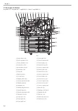
Sensor Clearing
method
Cassette 4 pickup sensor (PS47)
Open/close the cassette 4
Vertical path 4 sensor (PS56)
Open/close the lower right cover
Cassette 3 pickup sensor (PS41)
Open/close the cassette 3
Vertical path 3 sensor (PS55)
Open/close the lower right cover
Cassette 2 pickup sensor (PS34)
Open/close the cassette 2
Vertical path 2 sensor (PS54)
Open/close the lower right cover
Cassette 1 pickup sensor (PS28)
Open/close the cassette 1
Vertical path 0 sensor (PS26)
Open/close the manual feed tray cover
Vertical path 1 sensor (PS53)
Confluence sensor (PS27)
OHT sensor (PS5/6)
Secondary transfer sensor (PS13)
Open/close the front cover
Inside delivery sensor (PS15)
Reversal inlet sensor (PS17)
Reversal vertical path sensor (PS18)
Duplexing left sensor (PS19)
Duplexing middle sensor (PS20)
Duplexing right sensor (PS40)
Summary of Contents for imagePRESS C1
Page 1: ...Oct 22 2008 Service Manual imagePRESS C1 Series ...
Page 2: ......
Page 6: ......
Page 38: ...Contents ...
Page 39: ...Chapter 1 Introduction ...
Page 40: ......
Page 42: ......
Page 72: ...Chapter 1 1 30 F 1 18 ...
Page 85: ...Chapter 1 1 43 T 1 26 ...
Page 88: ......
Page 89: ...Chapter 2 Installation ...
Page 90: ......
Page 94: ......
Page 234: ......
Page 235: ...Chapter 3 Basic Operation ...
Page 236: ......
Page 238: ......
Page 244: ......
Page 245: ...Chapter 4 Main Controller ...
Page 246: ......
Page 248: ......
Page 276: ...Chapter 5 Original Exposure System ...
Page 277: ......
Page 332: ...Chapter 6 Laser Exposure ...
Page 333: ......
Page 342: ...Chapter 6 6 8 F 6 10 1 Laser Light 2 Laser Shutter 3 Laser Shutter Lever 1 1 2 2 1 2 3 3 3 3 ...
Page 344: ...Chapter 7 Image Formation ...
Page 345: ......
Page 431: ...Chapter 7 7 82 ...
Page 462: ...Chapter 8 Pickup Feeding System ...
Page 463: ......
Page 504: ...Chapter 8 8 39 7 F 8 52 8 F 8 53 9 F 8 54 1 3 2 1 2 4 3 1 2 4 3 ...
Page 505: ...Chapter 8 8 40 10 F 8 55 11 F 8 56 12 F 8 57 1 4 2 3 5 4 1 3 2 1 4 2 5 3 ...
Page 506: ...Chapter 8 8 41 13 F 8 58 14 F 8 59 15 F 8 60 5 1 2 3 4 1 2 3 5 4 1 2 3 4 5 ...
Page 507: ...Chapter 8 8 42 16 F 8 61 1 2 3 4 5 ...
Page 509: ...Chapter 8 8 44 3 F 8 64 A Duplexing reversal position 4 F 8 65 2 1 A 2 1 ...
Page 510: ...Chapter 8 8 45 5 F 8 66 6 F 8 67 2 1 2 1 ...
Page 511: ...Chapter 8 8 46 7 F 8 68 8 F 8 69 3 2 1 3 2 1 ...
Page 512: ...Chapter 8 8 47 9 F 8 70 10 F 8 71 3 2 1 2 3 1 ...
Page 513: ...Chapter 8 8 48 11 F 8 72 B Duplexing re pickup stop position 12 F 8 73 3 2 B 1 3 1 2 ...
Page 514: ...Chapter 8 8 49 13 F 8 74 14 F 8 75 1 2 3 1 2 3 ...
Page 516: ...Chapter 8 8 51 F 8 77 SL3 M10 PS17 ...
Page 533: ...Chapter 8 8 68 F 8 154 1 2 4 3 2 3 4 ...
Page 534: ...Chapter 9 Fixing System ...
Page 599: ...Chapter 10 Externals and Controls ...
Page 642: ...Chapter 11 MEAP ...
Page 643: ......
Page 645: ......
Page 695: ...Chapter 12 Maintenance and Inspection ...
Page 696: ......
Page 698: ......
Page 700: ...Chapter 12 12 2 F 12 1 28 9 10 14 13 29 29 11 12 27 6 3 1 2 5 4 7 8 15 16 ...
Page 701: ...Chapter 12 12 3 F 12 2 17 20 24 23 25 26 19 18 24 21 22 ...
Page 704: ...Chapter 12 12 6 F 12 3 1 2 3 4 9 6 5 7 8 11 12 13 14 15 10 ...
Page 715: ...Chapter 12 12 17 F 12 18 1 1 2 2 ...
Page 716: ...Chapter 13 Standards and Adjustments ...
Page 717: ......
Page 719: ......
Page 732: ...Chapter 14 Correcting Faulty Images ...
Page 862: ...Chapter 15 Self Diagnosis ...
Page 894: ...Chapter 16 Service Mode ...
Page 895: ......
Page 1222: ...Chapter 17 Upgrading ...
Page 1223: ......
Page 1225: ......
Page 1256: ...Chapter 17 17 31 F 17 65 2 Turn off the main power switch and remove the USB device ...
Page 1257: ...Chapter 18 Service Tools ...
Page 1262: ......
Page 1263: ......
Page 1264: ...Oct 22 2008 ...
Page 1265: ......


